
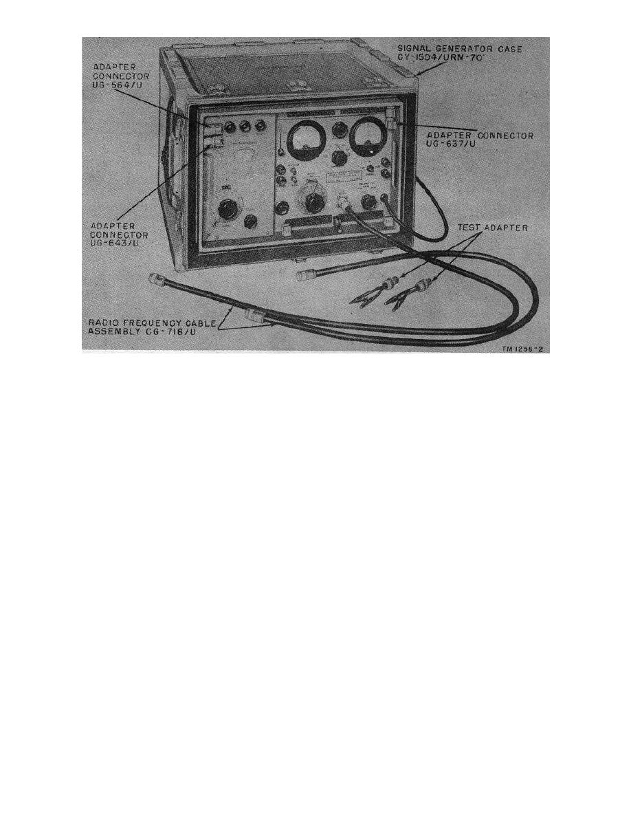
Figure 2. Signal Generator AN/URM-70, with cables and adapters.
4. Application
5. Technical Characteristics
Frequency range:
whenever an rf signal source with a frequency be-
Band A ------------------------ 60 mc to 100 mc.
tween 50 and 400 mc at a strength of .1 to 100,000
Band B ------------------------ 100 mc to 00 mc.
microvolts is required
Band C ------------------------ 200 mc to 400 mc.
Types of output:
b. A few of the applications of the signal gein-
Unmodulated rf-------------- 50 mc to 400 mc, con-
erator are listed below:
tinuous wave.
(1) Calibration of oscillators.
Frequency-modulated rf ----------
50 mc to 400 mc; inter-
(2) Measurement of receiver sensitivity.
nally modulated at
1,000, 1,600, or 20,000
(3) Measurement of signal plus noise-to-
cycles per second, or
noise ratio.
externally modulated
(4) Measurement of overall distortion.
at 250 to 70 kc.
(5) Determination of band-pass character-
Fm frequency deviation:
istics.
Band A
0 to 15 kc.
0 to 75 kc.
(6) Performance of alinement procedures.
-------------------------------- -- 0 to 150 kc.
(7) Measurement of stage gain.
Band B ------------------------ 0 to 30 kc.
(8) Measurement of discriminator charac-
0 to 150 kc.
teristics.
0 to 300 ke.
Band C ----------------------- 0 to 60 kc.
(9) Measurement of a receiver's image re-
0 to 300 kc.
ject,ion ratio.
0 to 600 ke.
4

