
TM 11-5841-283-12/NAVAIR 16-30APR39-1
1-13. BLOCK DIAGRAM PRESENTATION. (CONT)
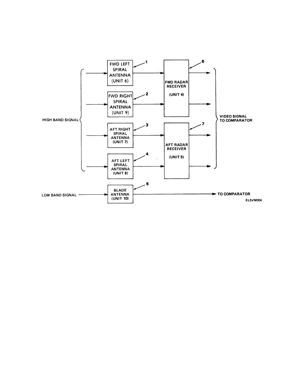
SIGNAL INPUT AND AMPLIFICATION
FORWARD LEFT SPIRAL ANTENNA (Unit 6). Picks up high band signals between
1.
0 - 90 relative to aircraft heading and transmits them to the forward radar receiver.
FORWARD RIGHT SPIRAL ANTENNA (Unit 9). Picks up high band signals between
2.
270 - 360 relative to aircraft heading and transmits them to the forward radar receiver.
3.
AFT RIGHT SPIRAL ANTENNA (Unit 7). Picks up high band signals between 90 - 180
relative to aircraft heading and transmits them to the aft radar receiver.
AFT LEFT SPIRAL ANTENNA (Unit 8). Picks up high band signals between 180 - 270
4.
relative to aircraft heading and transmits them to the aft radar receiver.
BLADE ANTENNA (Unit 10). Picks up low band signals and transmits them to the
5.
comparator. The blade antenna is omnidirectional.
FORWARD RADAR RECEIVER (Unit 4). Filters, detects, and amplifies the high band
6.
signals from the forward right and forward left spiral antennas. The radar receiver converts
high band signals to video signals.
AFT RADAR RECEIVER (Unit 5). Filters, detects, and amplifies the high band signals
7.
from the aft right and aft left spiral antennas. The radar receiver converts high band
signals to video signals.
1-11

