
TM 11-6625-2575-14
form to the layout of the replaced component.
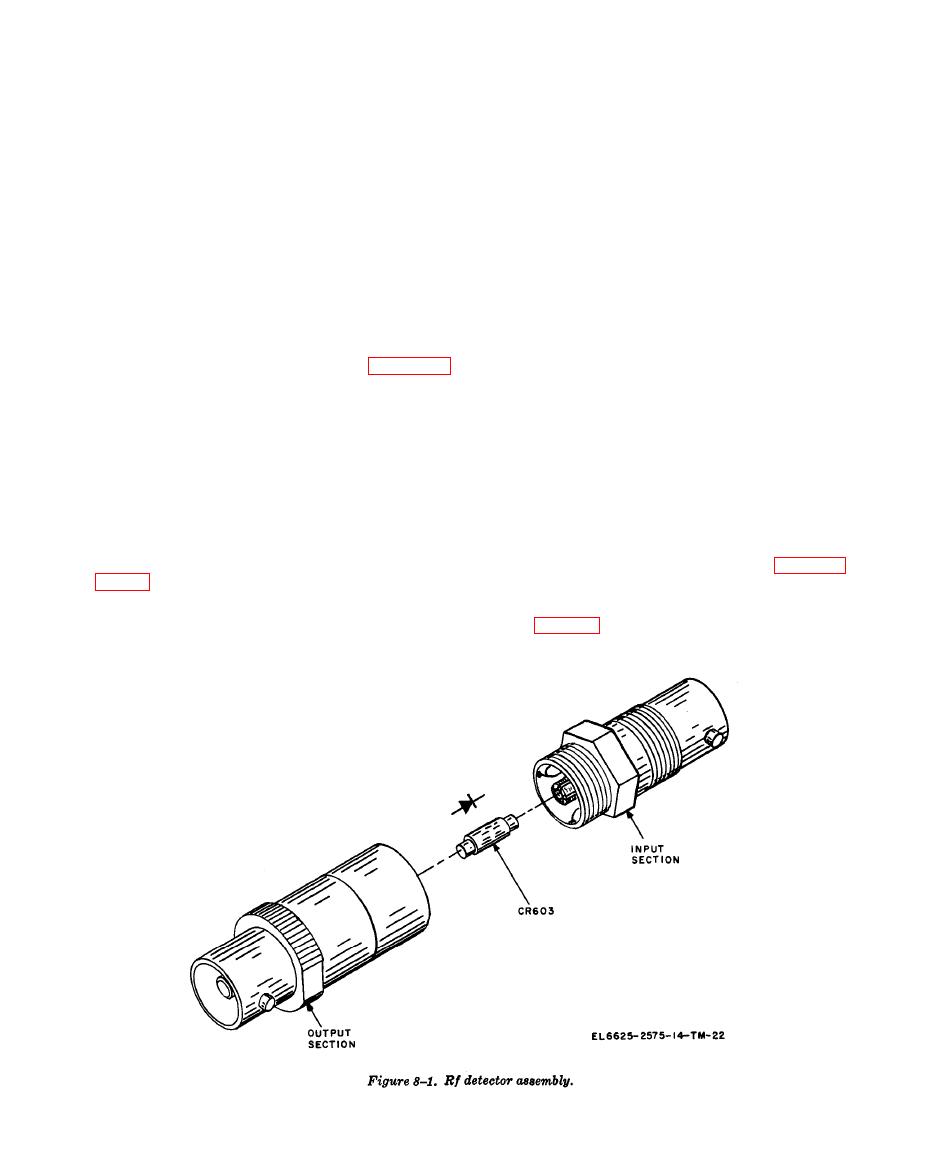
f. Observe the diode polarity for the negative
Failure to closely reconstruct the original layout
detector. The clamped end is the cathode which
may prevent normal operation of the AN/USM-
is color-coded green.
203A. The calibration or alignment procedure
g. Insert the new diode with correct polarity.
will normally provide compensation for new com-
h. Rejoin the two detector halves by tighten-
ponents and for min or changes in circuit geom-
ing the mating threads in a clockwise direction
etry.
with finger pressure only.
i. Install the rf detector assembly in the AN/
NOTE
USM-203A.
The diode only shall be replaced. If re-
placement of the diode does not correct
8-6. Monitor/Mixer Assembly
the defect, a replacement detector as-
sembly shall be installed.
Five components in the monitor/mixer assembly
require special instructions for removal or replace-
ment. These components are CR601, R602, R603,
7-2.
and R605. Unless the complete assembly is re-
b. Remove the BNC connector from the detec-
placed, removal of the front panel is unnecessary.
tor output.
CAUTION
c. Remove the rf detector assembly from the
Components in the monitor block are
front panel by removing the hex nut (RH
part of the ALC system. When removing
thread).
or replacing components, be careful to
d. Using finger pressure only, unscrew the two
duplicate the original positions as close-
halves of the rf detector in a counterclockwise
ly as possible.
direction for approximately 2 turns (RH thread).
Diode CR603 is clamped in the split bushing
ure 8-2 and proceed as follows:
(1) Remove the top AN/USM-203A dust
from the bushing.
cover (para 7-2).

