
TM11-6625-2948-14+P
(9) Set the RATE multiplier to X100.
(15) Observing pulse width on the oscilloscope, rotate the
PULSE WIDTH vernier counterclockwise until the pulse
(10) Rotate the RATE control vernier slowly clockwise.
width on oscilloscope decreases through 0.5 microseconds
The display should increase smoothly beyond a rate of
to a minimum of typically 0.2 microseconds.
4000 Hz to typically 10 kHz.
(16) Set the PULSE WIDTH vernier control for a pulse
(11) Set the PULSE WIDTH vernier control fully counter-
width of 1 microsecond as observed on the oscilloscope.
clockwise and multiplier switch to X10.
The rise and fall times should be <0.2 microseconds.
(12) Set the RATE control vernier fully counterclockwise
and multiplier switch to X100.
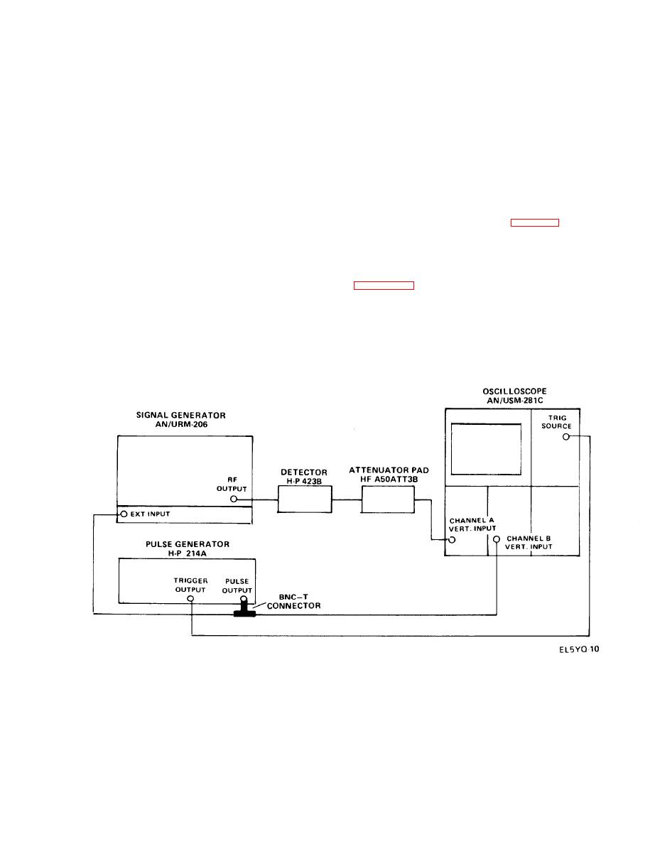
f. External Pulse Modulation Test.
(13) Rotate the PULSE WIDTH control slowly clockwise
(1) Connect equipment as shown in figure 4-2.
and observe that pulse display on the oscilloscope increases
smoothly until it goes beyond 10 microseconds to a maxi-
(2) Set FREQUENCY GHz dial to 9.0 GHz.
mum of typically 20 microseconds.
(3) CAL signal generator on CW for 0 dBm output. (See
(14) Set the PULSE WIDTH multiplier switch to X1.

