
TM11-6625-2948-14+P
(11) Repeat steps (2) through (10) except that the positive
(4) Set
the
MODULATION
SELECTOR
switch
to
amplitude output of the Pulse Generator HP 214A is
EXT
position.
changed to the negative polarity and the SELECTOR
switch of Modulator MD-1075/URM is switched to EXT(-).
(5) Set Modulator MD-1075/URM controls as follows:
Position
Control
g. Internal Frequency Modulation Test.
EXT
FUNCTION
EXT (+)
(1) Set FREQUENCY GHz control to 11.0.
SELECTOR
(2) Set
F control to 0.
(6) Set oscilloscope for dual trace observing input video
and output detected pulse signals. The input pulse will
(3) Set MODULATION SELECTOR switch to CW.
range from below 20 to above 70 volts and the output
pulse will be approximately 50 millivolts, depending on
the sensitivity of the detector used. Check that the rise and
( 4 ) Adjust POWER SET control for CAL on the power
monitor meter.
fall time of the input pulse is less than 0.2 microseconds.
(7) Set the HP 214A pulse generator PULSE WIDTH con-
(5) Set A T T E N U A T O R control to read 0 dBm output on
the attenuator dial.
trol to 0.5 microseconds and INT. REP. RATE to 100 kHz.
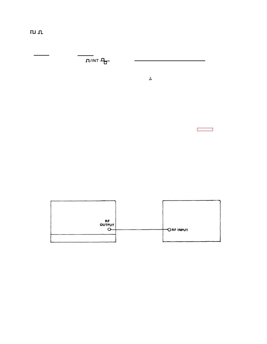
(6) Connect equipment as shown in Fig. 4-3.
AMPLITUDE control is varied from 20 to 70 volts peak.
(7) Adjust the controls on spectrum analyzer to locate the
11.0 GHz signal and display it in the center of the CRT
(9) Set Pulse Generator HP 214A for 70 volts, 10 Hz.
screen.
(10) Observe oscilloscope display for a steady output pulse
( 8 ) Set the MODULATION SELECTOR switch to EXT
as the pulse generator width is varied from 0.5 to 2500
FM.
microseconds.
S P E C T R U M ANALYZER
S I G N A L GENERATOR
H-P 8555A
AN/URM-206
EL5YQ-11

