
TM11-6625-2948-14+P
(13) Repeat steps (1) through (12) at 7.0, 8.0, 9.0 and
(9) Set the controls on Modulator MD-1075/URM as
10.0 GHz.
follows:
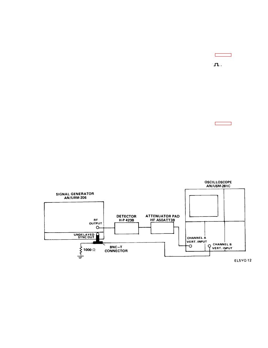
h. Internal Synchronization Test.
Position
Control
(1) Connect equipment as shown in Fig. 4-4.
FM
FUNCTION switch
(2) Set FUNCTION switch to INT
.
INT
SELECTOR switch
(3) Set SELECTOR switch to INT.
X100
RATE switch
(4) Measure the amplitude, polarity, and pulse width.
APPROX. MIDDLE
RATE Vernier
The synchronizing signal should be of positive polarity
between 25 to 100 volts in amplitude with a maximum
pulse width of 5 microseconds.
(10) Rotate the FM DEV AMPLITUDE control clockwise
until an FM deviation of 5 MHz nominal is indicated on the
i. External Synchronization Sine Wave Test.
analyzer.
(1) Connect equipment as shown in Fig. 4-5.
( 1 1 ) Rotate the RATE vernier slowly counterclockwise
and observe that 5 MHz FM deviation is still indicated on
(2) Set FREQUENCY GHz control to 9.00 GHz.
the analyzer.
( 3 ) Set MODULATION SELECTOR switch to CW and
(12) Switch the RATE switch to X1 and set the RATE
adjust the POWER SET control for an indication of CAL
vernier approximately in the middle. Observe that 5 MHz
on the power level monitor meter.
deviation is still indicated on the analyzer.

