
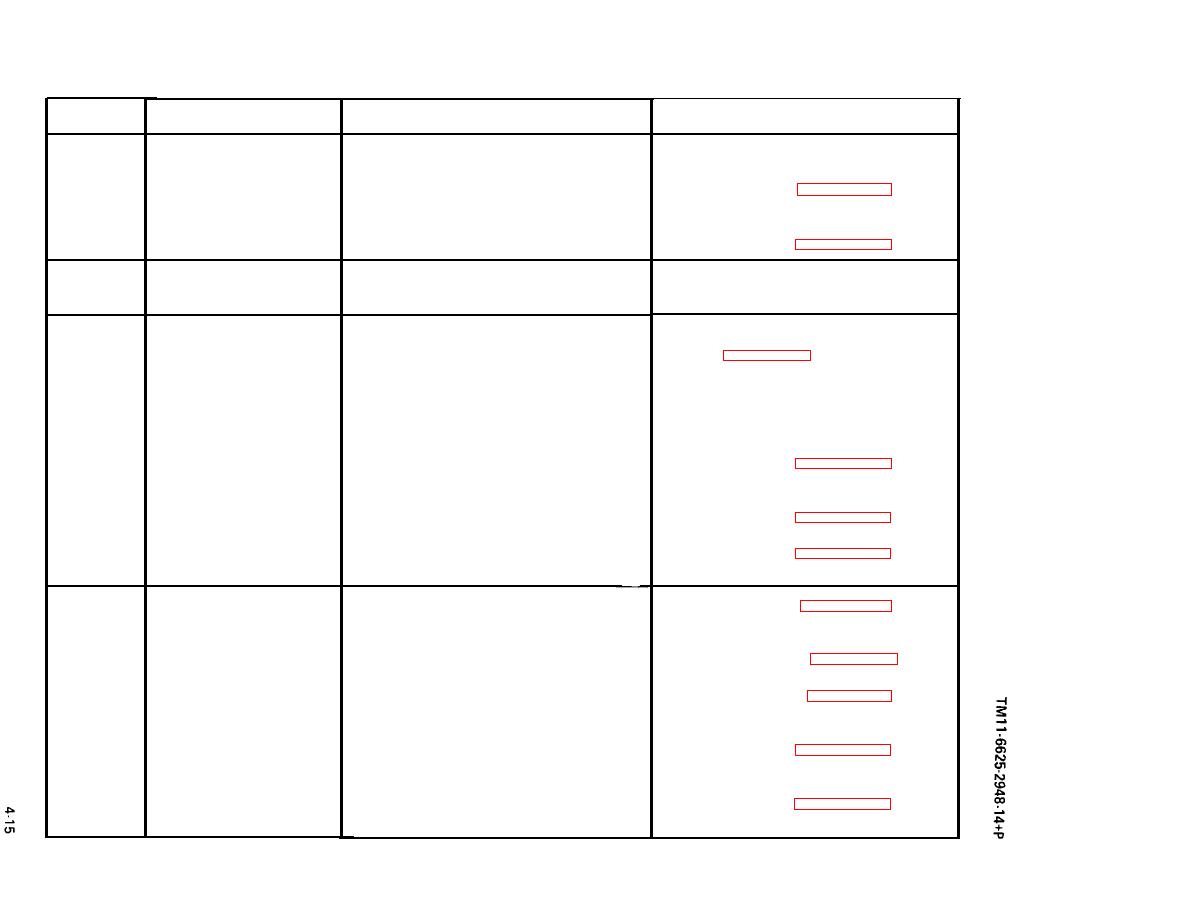
TABLE 4-2. TROUBLESHOOTlNG CHART (Continued)
Probable Cause
Step
Corrective Action
Symptom
Replace cable
c.
Defective video cable C147363
13
c.
(cont'd)
Replace 1A3 (see paragraph 4-6d.)
d.
d. Broken wire on Pushbutton Board Assy
1A3
Defective switch 1A3S1
Replace 1A3 (see paragraph 4-6d.)
e.
e.
No external pulse
14
Same as Step 12
Same as Step 12
modulation
Defective Modulator MD-1075/URM
Replace Modulator MD-1075/URM
15
a.
a.
N O internal FM operation
(AN/URM-206)
(see paragraph 4-6a.)
Defective video cable C147363
b.
b. Replace cable
(between FM OUT and EX FM
connectors)
Replace 1A3 (see paragraph 4-6d.)
c.
Defective amplifier circuitry (1A3Q1
c.
and associated circuitry or 1A3U2)
Replace 1A3 (see paragraph 4-6d.)
d.
Defective switch 1A3S1
d.
Broken wire on Pushbutton Board
e. Replace 1A3 (see paragraph 4-6d.)
e.
Assembly 1A3
Defective amplifier circuit (1A3Q1
a.
Replace 1A3 (see paragraph 4-6d.)
No internal FM
16
a.
(Model SG-1145/URM)
and associated circuitry or 1A3U2)
b. Replace
b. Defective switch 1A3S1
1A3 (see paragragh 4-6d.)
No ac voltage between pin 2 of
Replace
c.
1A2 (see paragraph 4-6c.)
c.
1A3U2 and ground
d. Replace 1A3 (see paragraph 4-6d.)
d. Broken terminal T3, T4, and T5
on Pushbutton Board Assy 1A3
Replace 1A3 (see paragraph 4-6d.)
e. Defective in FM DEV potentiometer
e.
1A3R16

