
TM 11-6625-3041-12/TO 33A1-8-908-1
1-18. ERROR DETECTION (cont)
BER
GO BER: A BER Duration Counter counts the number of clock
pulses, which represent the number of data bits recei ved,
Indicators
After it has counted 1,000,000 clock pulses (200,000) for the
.6-32 data rate family) it produces a Normal End pulse. This
pulse initiates the action of the Green Control circuit which
lights the green GO lamp, indicating the bit error rate was
less than 10 per million (1 per 100,000). The Normal End pulse
also resets to zero the BER Duration Counter and the counters
in the the Yellow and Red Control circuits.
NO GO BER: The errors from the Error Detector are also applied
to a counter in the Yellow and Red Control circuits. After the
BER Duration Counter has counted 100,000 clock pulses (10,000
for the .6-32 data rate family) it produces a Red End pulse.
This pulse resets the counter in the Red Control circuit to
zero. If, before being reset, the counter reaches a count of
100 (10 for the .6-32 data rate family) the Red Control circuit
lights the red NO GO lamp, indicating the bit error rate was
equal to or greater than 100 per 100,000. The output from the
Red Control circuit also inhibits the operation of the Yellow
and Green Control circuits and resets the BER Duration Counter
to zero.
MARGINAL BER: If the counter in the Yellow Control circuit
reaches a count of 10 (2 for the .6-32 data rate family), the
Yellow Control circuit lights the yellow MARGINAL lamp, indi-
cating the bit error rate was equal to or greater than 10 per
million (1 per 100,000). The output from the Yellow Control
circuit also inhibits (prevents the operation of) the Green
Control circuit.
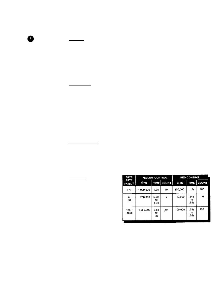
Summary: Although
the normal BER dura-
tion is fixed at 1
million bits
(200,000 for the
.6-32 data rate
family) the actual
time it takes to
count these bits
depends on the DATA
RATE setting.
1-19/1-20 blank

