
TM 11-6625-3041-30/TO 33A1-8-908-12
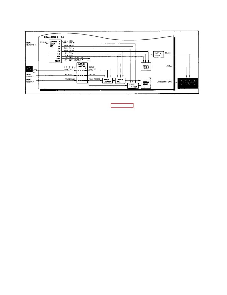
1-18. TRANSMIT 2 (A4) ERROR COUNT
The divide-by-16 output (32/36 kHz) from the Diphase Clock Gen
Control
on the Transmit 2 card (para 1-14, Diphase Clock Gen) is applied
Clock Gen
to the input of the Control Clock Gen.
The Control Clock Gen has eight different divider outputs. Each
output can be one of two different rates, depending on whether
the DATA RATE control has set the Master Osc for an output of
8.192 or 9.216 MHz.
The 3.9/4.4 Hz output from the Control Clock Gen is applied
Display
through the Display Control as a blink input to the Error
Control
Counter.
When the front panel LAMP TEST pushbutton is pressed, the
O-level signal is applied through the Display Control as a
Load input to the Error Counter. This loads an 8 into each
of its 7-decade dividers.
The initialize signal from the BER Control on the Receive 2 card
is applied through the Display Control as a clear input to the
Error Counter, which sets a O into each of its 7-decade counters.
The true errors signal from the Error Shape on the Receive 1
card is applied through the Display Control to the input of
the Error Counter, which advances its count by one each time
a true-errors pulse is received.

