
TM 11-6625-3041-30/T0 33A1-8-908-12
1-18. TRANSMIT 2 (A4) ERROR COUNT (CONT)
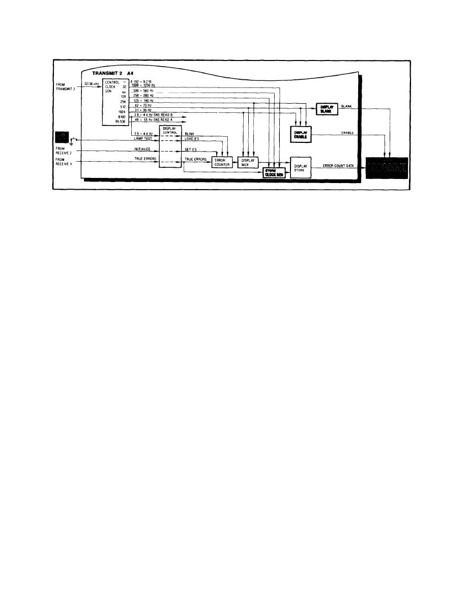
Store
The Store Clock Gen is driven by the true-errors signal
Clock Gen
through the Display Control, and by three outputs from the
Control Clock Gen 1000/1250, 500/560, and 250/280 Hz).
Its output is used to transfer the error-count data in the
Display Store to the ERRORS display. The true-errors input
prevents the transfer of data during the time the count in the
Error Counter would be changing.
Display
The Display Enable consists of a single 1-of-7 selector whose
Enable
output is determined by the same three inputs as the selectors
in the Display Mux.
ERRORS
The ERRORS display consists of a 7-digit LED display
corresponding to the seven decades in the Error Counter. The
Displays
4-bit error-count data from the Display Store is applied to all
seven display digits.
The enable signals from the Display Enable allow only one dis-
play digit at a time to accept the error-count data. The digit
selected corresponds to the decade selected in the Error Counter.
Since both the Display Mux and Display Enable are driven by the
same three clock signals, the decade selected for output and
the digit selected for input are identical.
In this way, the 28-line data (7 decades x 4 bits) is reduced to
11-line data (7 enable signals + 4 bits) in order to minimize
wiring.
The 62/70 Hz output from the Control Clock Gen is applied to the
Display
Display Blank. Its output is applied to the ERRORS display and
Blank
is used to blank the display at a 62 to 70 Hz rate in order to
minimize power consumption.
1-20

