
TM 11-6625-3041-30/TO 33A1-8-908-12
1-19. RECEIVE 2 (A6) BIT ERROR RATE (CONT)
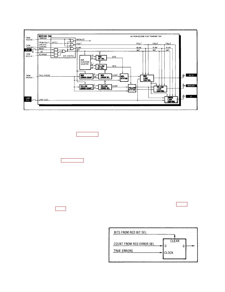
The 104 and 105 outputs from the BER Duration Counter are
Red
Bit Sel
applied to the Red Bit Sel. The input selected for output
depends on the setting of the front panel DATA RATE control
through the 04 output from Decode II on the Transmit 2 card
(refer to para 1-12, DATA RATE Control). A setting for the 576
or 128-4608 families causes an 04 output to zero, which selects
the 105 input as the output. A setting for the .6-32 family
causes an 04 output of 1, which selects the 104 input.
True errors from the Error Shape on the Receive 1 card (refer
Red
to para 1-17, Error Shape) are applied to the Red Error Count,
Error Count
which counts the errors.
The counter produces two outputs: one after 10 errors have
been counted (10) and one after 100 errors have been counted
(100).
The 10 and 100 outputs from the Red Error Count are applied to
Red
the Red Error Sel. The input selected for output depends on
Error Sel
the setting of the front panel DATA RATE control through the 04
output from Decode II on the Transmit 2 card (refer to para
families causes an 04 output of zero, which selects the 100
input as the output. A setting for the .6-32 family causes
an 04 output of 1, which selects the 10 input.
The Red Status is a
Red
data flip-flop whose
Status
D input is the out-
put from the Red
Error Sel.
1-22

