
TM
11-6625-3041-30/TO
33A1-8-908-12
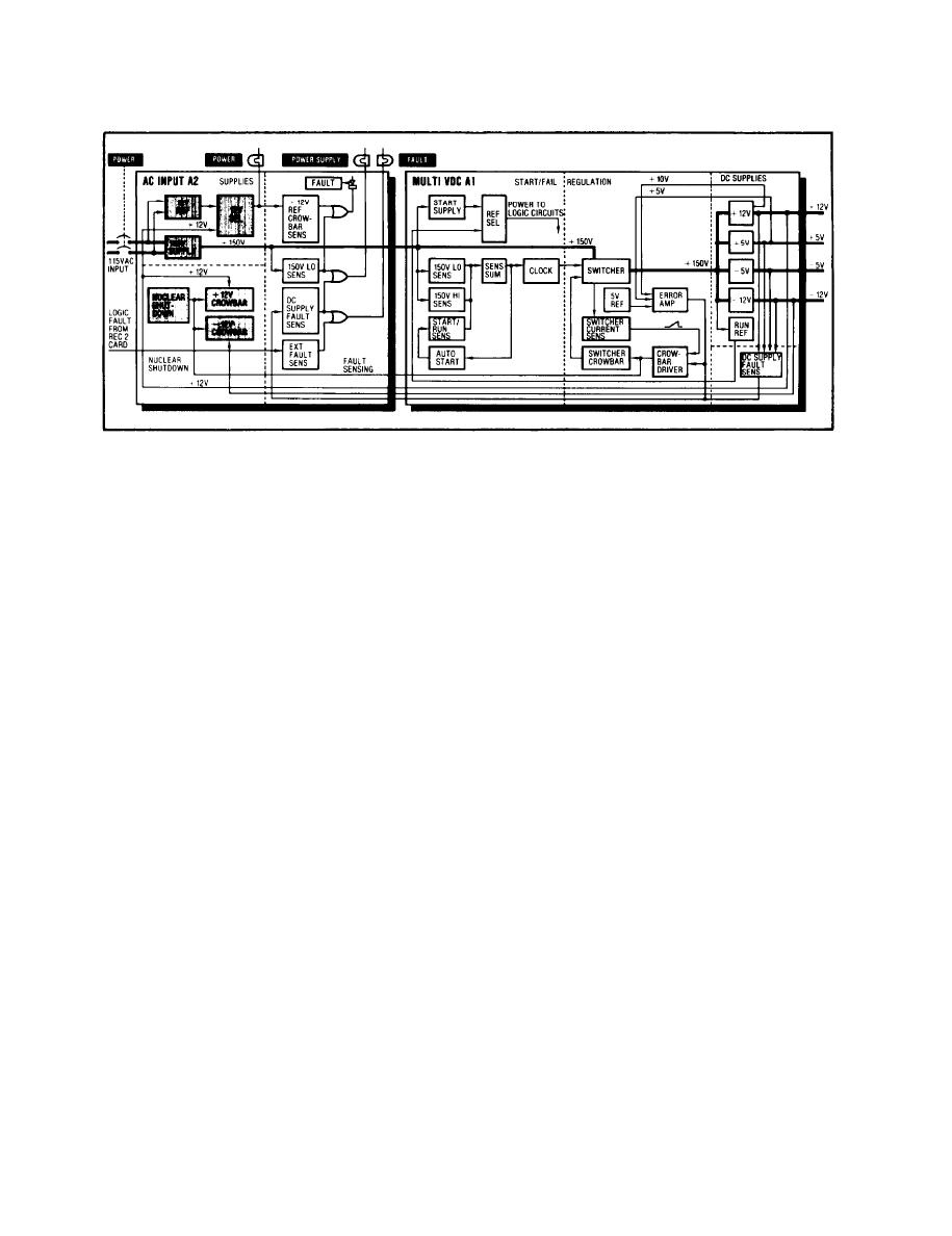
1-21. AC INPUT (A2) SUPPLIES
AC Power
AC power is applied to the POWER input, a combination connector
and filter FL1 on the rear panel. Both sides are switched by
the POWER control circuit breaker CB1 on the front panel. The
hot side is applied through a jumper on the Multi VDC card to
the 12V and 150V supplies. If the Multi VDC card is removed,
the AC Input card is deprived of ac power and will not operate.
AC power is applied to the 12V Reference supply where it is
12V Ref
stepped down by T1, rectified by CR10, 12, 14, and 16, filtered
by C8 and 9, and regulated by VR1.
The 12V Reference output is applied to the 12V Sel at the anode
12V Sel
of CR25. Two other inputs are applied to the 12V Sel circuit,
one at the anode of CR17 (which is not used in the SG-1139) and
one at the anode of CR24.
The 12V Reference output is used only during start up. Once
the Switcher on the Multi VDC card is operating, the +12V(B)
input rises to +12V and backbiases CR25. This prevents the
12V Reference from supplying the 12V(J) line which, instead,
is supplied by the normal 12V dc supply (+12V(B)) on the
Multi VDC card.
The +12V(J) line is used to power circuits on both the AC Input
and Multi VDC cards. It also lights the POWER indicator DS1 on
the front panel and supplies power for the ALARM indicators
(POWER SUPPLY fault DS2, and FAULT summary DS3) on the front
panel .
AC power is also applied to the 150V supply where it is recti-
150V supply
fied by CR20 through CR23 and applied through R27 to the
Multi VDC card. R27 limits the surge current at turn on.
Once the Switcher on the Multi VDC card is operating, the Soft
Start Inh input to Q6 gate goes positive and turns on Q6. With
Q6 on, R27 is bypassed and the full current from the 150V Supply
is allowed to pass to the Multi VDC card.

