
TM 11-6625-3041-30/TO 33A1-8-908-12
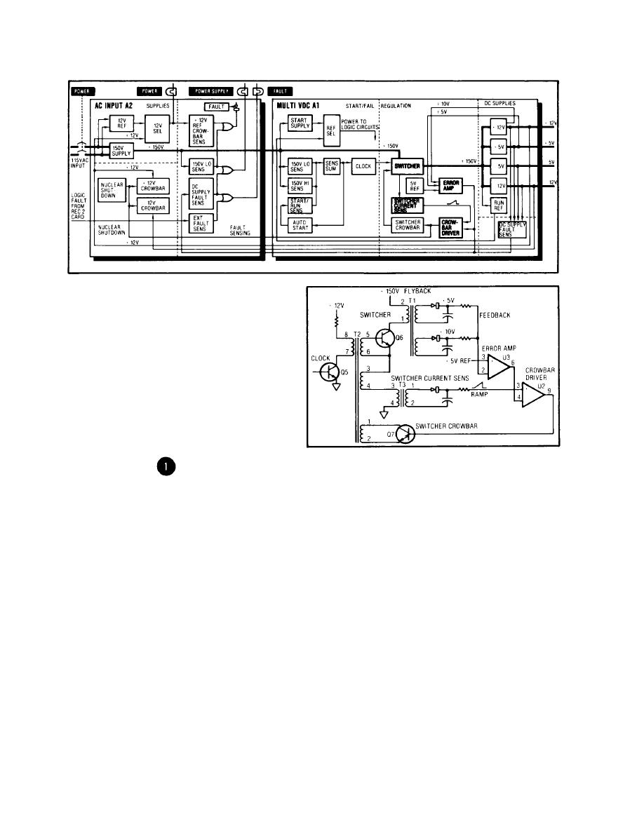
1-26. MULTI VDC (A1) REGULATION
The Clock output
Switcher
drives the Switcher
through T2. The
Switcher is in
series with a 150V
path that consists
of T1 primary (ter-
minals 2 and 1),
the Switcher Q6, T2
secondary (terminals
3 and 4), and T3
primary (terminals 3
and 4).
When the Clock out-
put Q5 turns off, its collector goes high. This positive
transition is coupled through T2 to the input of the Switcher
at Q6 base. Q6 turns on and current begins to increase through
it and T3 primary.
With the Switcher on, the voltage at T2 secondary terminal 3
goes high. This positive transition is coupled back to T2
secondary terminal 5 at the base of Switcher Q6, which rein-
forces the positive voltage from the Clock output in a positive
feedback loop similar to a multivibrator.

