
TM 11-6625-3041-30/TO 33A1-8-908-12
2-6.
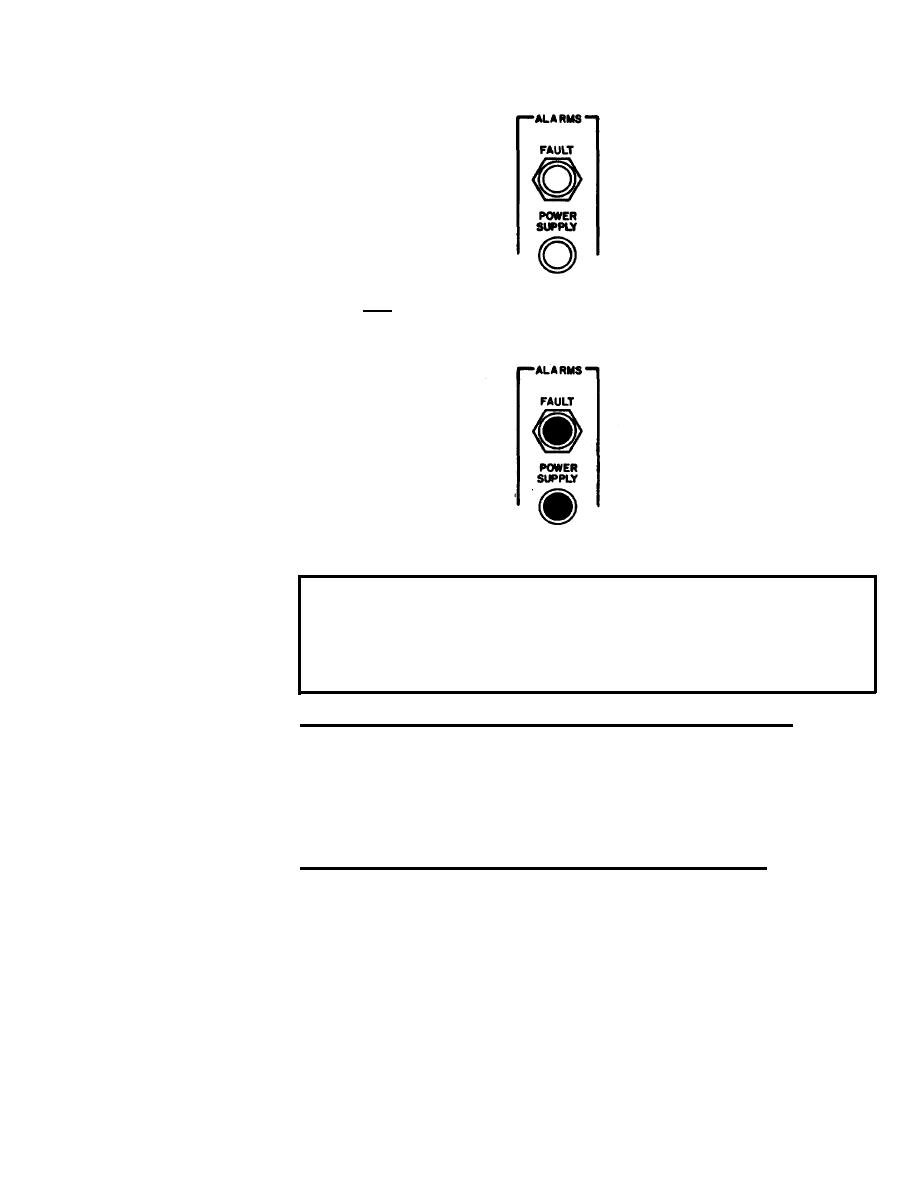
SG-1139 CHECK PROCEDURE (CONT)
Step Alarm
Set controls as
q
follows:
Indicators
2
POWER . . . ON
TIMING . . STA CLK
Red FAULT and
POWER SUPPLY
alarm indicators
must not be lit
Press and hold LAMP TEST pushbutton:
q
Red FAULT and
POWER SUPPLY
alarm indicators
must light.
If both parts
of this step
pass, release
LAMP TEST push-
button and pro-
ceed to step 3.
This step checks the following:
AC Input card . . . 150V supply
Multi VDC card . . All
Case Assembly . . . LAMP TEST pushbutton
Alarm indicators
If both indicators are lit before LAMP TEST is pressed:
Remove POWER SUPPLY access cover (refer to TM 11-6625-3041-12)
and note which card contains a lit fault indicator. Replace
that card (if both cards contain a lit indicator, or if no
card contains a lit indicator, replace AC Input card A2), and
repeat step 2.
If one indicator is lit before LAMP TEST is pressed:
Replace AC Input Card A2 (refer to TM 11-6625-3041-12), and
repeat step 2.

