
TM 11-6625-3041-30/TO 33A1-8-908-12
2-6.
SG-1139 CHECK PROCEDURE (CONT)
Step Diphase
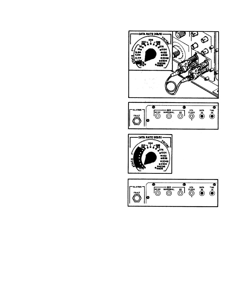
Set controls as
q
follows :
10
In
POWER . . . . . . ON
TIMING . . . . . MASTER
DATA RATE . . 0.6
Use two BNC
adapters and a
BNC cable to
connect DIPHASE
OUT to DIPHASE
IN:
Green TMG IN
and DATA IN
indicators must
light. Red
FAULT indicator
must not light.
Set DATA RATE to
0.6 through 32:
At each setting,
TMG IN and DATA
IN indicators
must light.
If both parts of this
step pass, proceed to
step 11. Keep cables connected.
This step checks the following:
Accessories . . . . . . BNC adapters
BNC cable
Case Assembly . . . . DIPHASE OUT and IN HV protect circuits on
transformer card
Receive 1 card . . . DIPHASE IN amplifier
DIPHASE IN sensor
Control Filter . . . DIPHASE OUT and IN connector
2-17

