
TM 11-6625-3051-12
(1)
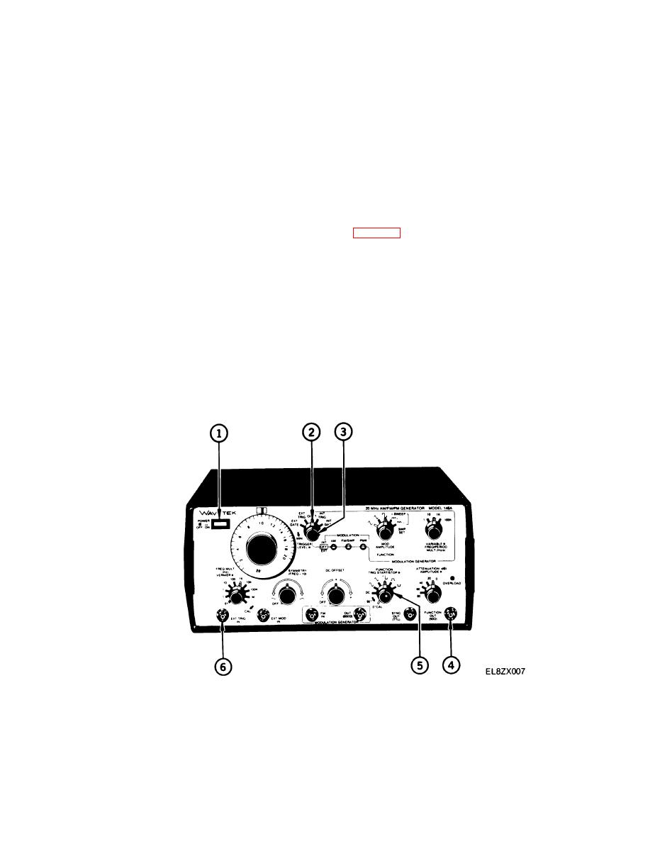
Set POWER OFF/ON switch (1) to OFF.
(2)
Connect a 50 ohm BNC to BNC coaxial cable to the FUNCTION OUT (50 Ω) connector (6). Terminate
(3)
remaining end with a 50 ohm feedthrough load.
Connect terminated end of BNC cable to test equipment.
(4)
Set POWER OFF/ON switch (1) to ON.
(5)
Set signal generator controls as indicated in table 2-4 (Continuous Mode Control Setup Positions).
(6)
Set FUNCTION switch (7) to desired waveform position.
(7)
Set generator Mode switch (2) to INT TRIG.
(8)
Adjust TRIGGER LEVEL control (3) to produce triggered output.
(9)
Rotate VARIABLE control (4) counterclockwise or FREQ/PERIOD MULT (Hz/s) switch (5) to adjust
(10)
trigger interval.
c.
External Triggered Mode. Operation is basically the same as in the internal triggered mode with the
exception that the signal generator will output a single cycle of the main frequency for each external trigger input.
The frequency is varied at the external trigger source to provide triggers of different intervals. Use the following
steps to operate the signal generator in the external triggered mode.
Set POWER OFF/ON switch (1) to OFF.
(1)
(2)
Connect a 50 ohm BNC to BNC coaxial cable to the FUNCTION OUT (50 Ω) connector (4). Terminate
(3)
remaining end with a 50 ohm feedthrough load.
2-9

