
TM 11-6625-3053-14
b. Attach the four feet, using the same mounting screws, to the location provided on the rear panel near the
blower filter. See Figure 1-2 for storage location of feet.
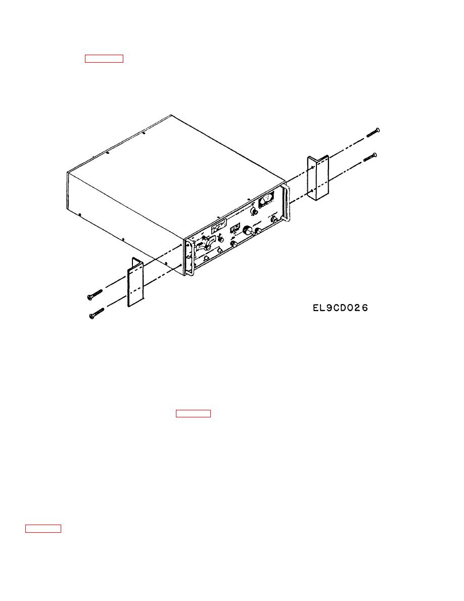
c. Remove rack mounting kit from plastic bag and attach one bracket to each side of dust cover by means of
the four screws furnished.
d. Mount the instrument in the open rack space (5-1/4 inches) using standard rack mount screws furnished with
the rack.
e. Attach power cord to rear panel receptable of instrument. Do not plug into power source before observing
procedure outlined in para 2-4b. through 2-4f.
4-8. PREPARATION FOR STORAGE OR SHIPMENT.
Since the signal generator was shipped in a specially designed set of packaging which should have been returned
through supply channels for storage (see para 2-3), this material should be re-used when storing or shipping the
equipment.
SECTION III. PREVENTIVE MAINTENANCE CHECKS & SERVICES,
TROUBLESHOOTING, AND MAINTENANCE
4-9. PREVENTIVE MAINTENANCE CHECKS & SERVICES.
Organizational Maintenance is authorized to perform all Operator PMCS. See Chapter 2, Section II for this information.
4-10. ORGANIZATIONAL TROUBLESHOOTING PROCEDURES.
Table 4-1 below lists the common malfunctions you may find which prevent the AN/USM-213B from operating. You
should perform the checks/inspections in the order listed.
4-2

