
TM 11-6625-3053-14
STEP
OPERATION
NORMAL INDICATION
CORRECTIVE ACTION
5
Set sig gen to initial settings of para 2-4, except turn the klystron mode
modulator output
(cont'd)
knob fully counter clockwise. Set freq counter to measure up to 2500 MHz.
Energize the system and set sig gen MODULATOR switch to EXTERNAL FM.
NOTE
If a component of the repeller tracking voltage circuit has been
replaced, such as the A4R1 repeller pot or the HIGH mode pot, set
all of the adjustable pots to their center positions. If only the klystron
has been replaced, leave the pot settings as they were.
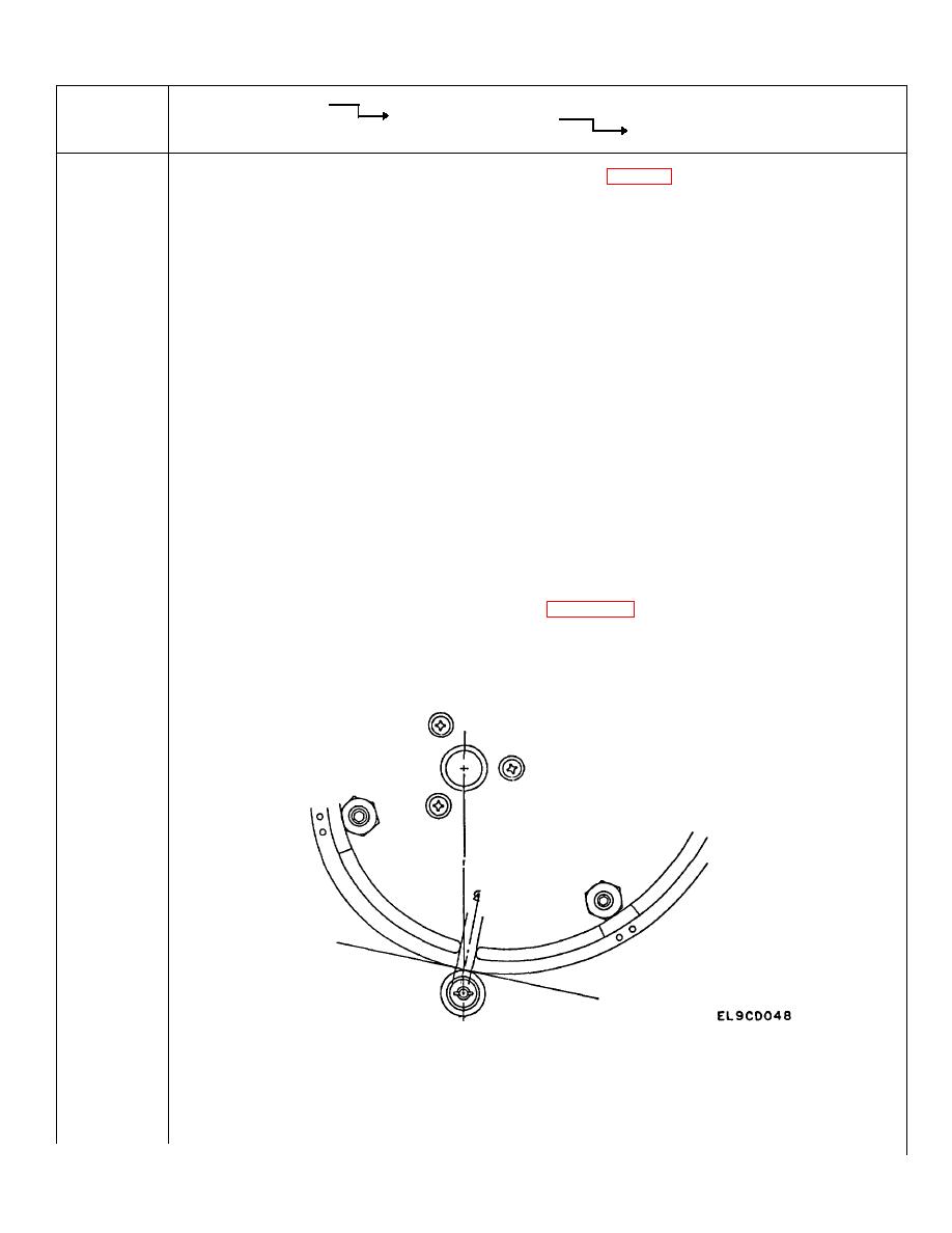
The following procedure concerns alinement of the tracking pots and the frequency tab points. Refer
to Figure 6-10.
Set the frequency control of the signal generator to 1520 MHz, the frequency which corresponds to
the center of the solid point on the frequency cam. The frequency counter should display 1520 MHz
+/- 1 MHz.
NOTE
A line from the center of the cam follower to the center of the cam
shaft intersects the cam surface at the center of the solid portion of
the cam. See point 4 on the cam, Figure 6-10 for detail below.
This delicate setting should not be altered unless you
have reason to believe the cam has shifted, or unless
you have replaced the cam. If either of these is the
case:
INITIAL CAM POSITIONING RELATIVE TO SOLID PORTION
6-34

