
TM 3-1040-276-10
2-1. CONTROLS AND INDICATORS (Cont).
Control or
Function
Indicator
Key
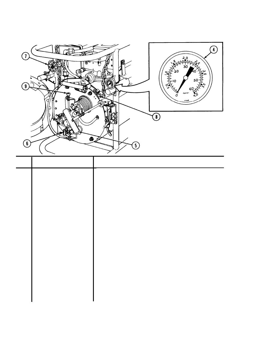
Mounted on air accumulator assembly. Indicates amount of air pres-
Air pressure gage
4
sure in pounds per square inch gage (psig). Pumping handle on air
pump assembly pressurizes air accumulator assembly. Dial moves
from 0 to 60 psig as air accumulator is pressurized. Pressing air
release button on air accumulator moves dial from 60 to 0 psig.
Pumping handle on air pump assembly pressurizes air accumulator
Air pump handle
5
assembly.
Located below float bowl. Used to control flow of fuel from float bowl.
Float bowl toggle valve
6
Moving toggle lever up opens valve and allows fuel to flow. Moving
toggle lever down closes valve and stops fuel flow.
Located above float bowl at front of engine. Controls flow of fog oil to
Oil metering globe valve
7
engine tube. Turning handle counterclockwise opens valve and
allows fog oil to flow. Turning handle clockwise closes valve and
stops all flow to engine tube.
Control valve with dust and moisture proof boot located on air accu-
Air release button
8
mulator assembly. Controls release of starting air to engine head
assembly. Pressing button releases pressurized air from air accumu-
lator to start engine.
Allows float bowl to be raised or lowered when pressed. Locks float
Float bowl adjustment knob
9
bowl in place when released. Raising float bowl increases fuel flow to
engine head assembly. Lowering float bowl decreases fuel flow.
2-2

