
TM 32-6625-022-24&P
f. Adjust FINE TUNING control to position 200 MHz
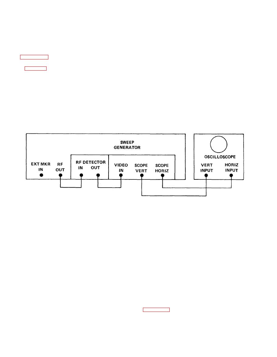
4-19 MARKER CIRCUIT.
marker near center of oscilloscope trace.
g. Adjust R303 (MKR AMPL ADJ) to obtain a marker
a. Set front panel controls to positions described in
amplitude of 100 mV peak-to-peak.
h. Set 50 MHz INT MARKER switch to OFF and 10
MHz INT MARKER switch to ON.
in figure 4-19.
i. Adjust R302 (MKR AMPL ADJ) to obtain a marker
c. Set 50 MHz INT MARKER switch to ON.
amplitude of 100 mV peak-to-peak.
d. Set SWEEP WIDTH control to NARROW and rotate
j. Set 10 MHz INT MARKER switch to OFF and the
SWEEP WIDTH ADJUST control approximately 1/4 CW.
1 MHz INT MARKER switch to ON.
e. Adjust RF OUTPUT control for an indication of 0.5
k. Adjust R301 (MKR AMPL ADJ) to obtain a marker
Vrms on RF OUTPUT meter.
amplitude of 30 mV peak-to-peak.
Section V. DIRECT AND GENERAL SUPPORT TESTING PROCEDURES
the signal generator. For test and procedures refer to
procedures are to be used to determine the serviceability of

