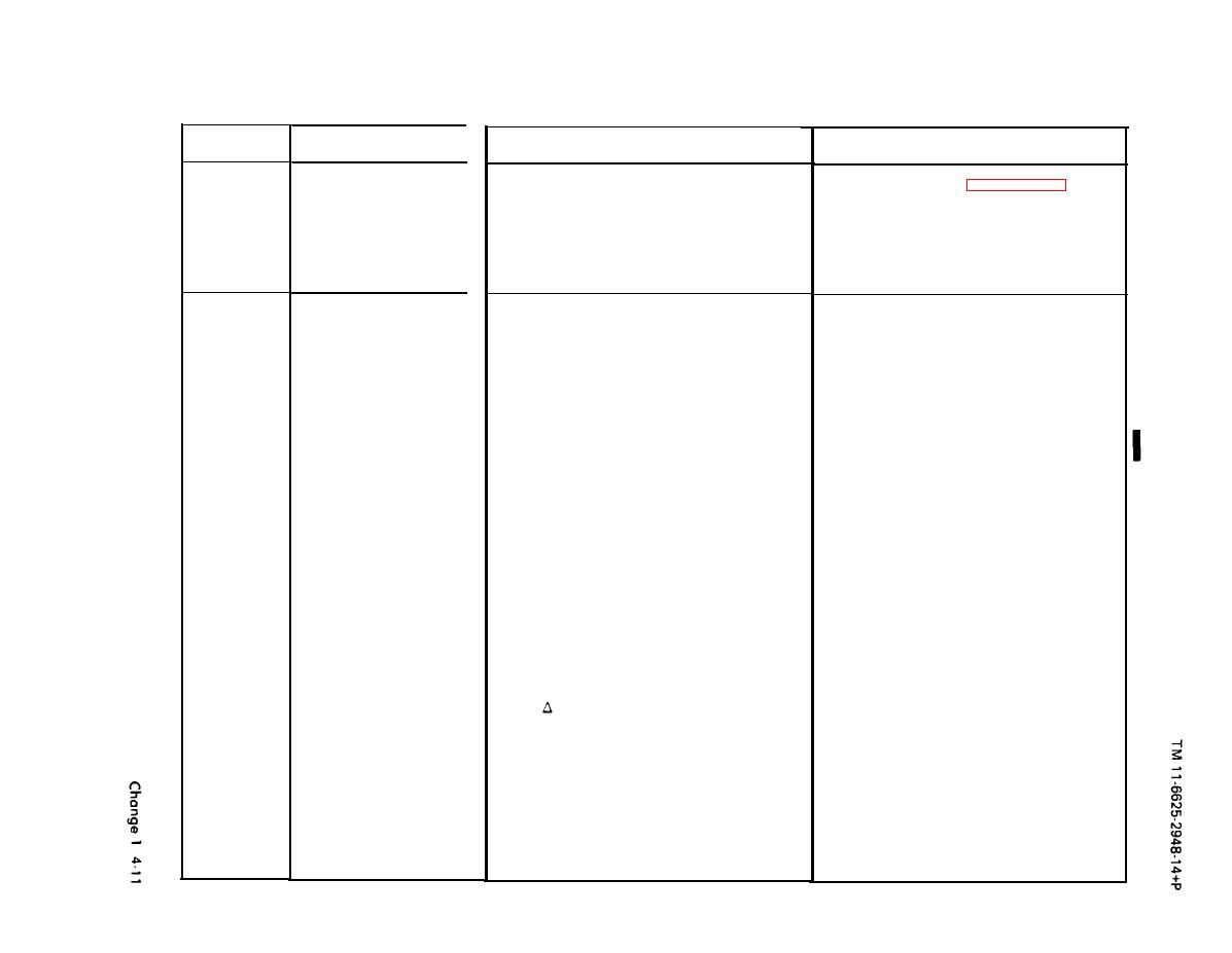
TABLE 4-2. TROUBLESHOOTING CHART (Continued)
Step
Symptom
Probable Cause
Corrective Action
2
60 to 400 Hz Converter Board 1A10
c. Replace 1A10 (see paragraph 4-6i.)*
C.
(cont'd)
defective
d. Defective fan 1B1
d.
Replace fan 1B1
Defective cable assembly 1W1
e.
e. Replace cable assembly 1W1
3
CW operation: No meter
a.
No RF OUTPUT (measure rf power at
CAL obtainable
the RF OUTPUT connector
(1) Replace fuse 1A4F1
(1) Faulty fuse 1A4F1
(2) Faulty fuse 1A4F2
(2) Replace fuse 1A4F2
(3) Faulty fuse 1A3F1*
(3) Replace fuse 1A3F1*
(4) No 6.3 vdc filament voltage between
(4) See Step 4
pins 2 and 3 of connector 1A3J3
(5) No beam voltage (- 1250 V) between
(5) See Step 6
pin 3 or 4 of connector 1A3J3
and ground
(6) N O repeller voltage between pin 3 of
(6) See Step 7
connector 1A3J5 and ground.
Note
F control should be turned fully
clockwise to measure -1850 V.
(7) No beam current (Measure voltage
(7) See Step 9
between ground and 1A4TP4)
(8) No oscillator power supply voltage
(8) See Step 5
(+30 V) between ground and 1A4TP1
I *Serial Numbers 2-60A thru 2-117A


