TM 11-6625-3041-30/TO 33A1-8-908-12
1-26. MULTI VDC (A1) REGULATION (CONT)
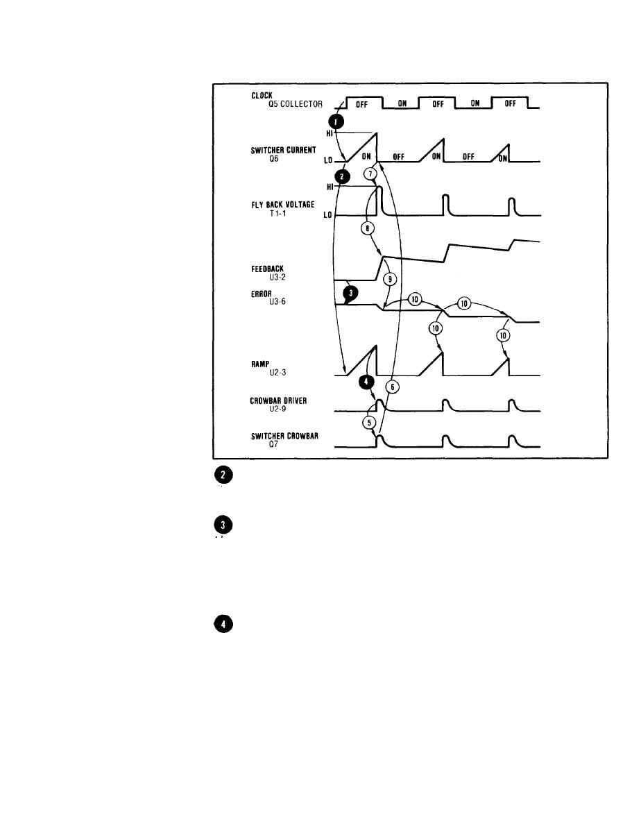
The voltage at T3 secondary is proportional to the current
Switcher
through T3 primary. This voltage ramp is applied to the posi-
Current
tive input of a differential amplifier (Crowbar Driver) at U2-3.
Sens
The negative input to the Crowbar Driver at U2-4 is from
Crowbar
Driver,
the output of another differential amplifier (Error Amp) at
U3-6. The positive input at U3-3 is a constant +5V reference
Error Amp
voltage. The negative input at U3-2 is a feedback voltage
derived from the +5V and +1OV dc supplies. At turn on the dc
supplies are at zero so that the output of the Error Amp at
U3-6 is high (about +11.8V).
As the ramp voltage rises, it eventually becomes more
positive than the error voltage at U2-4 from the Error Amp
output . This sets the Crowbar Driver output at U2-9 high.
1-37


