
TM 11-6625-2575-14
OPERATING INSTRUCTIONS
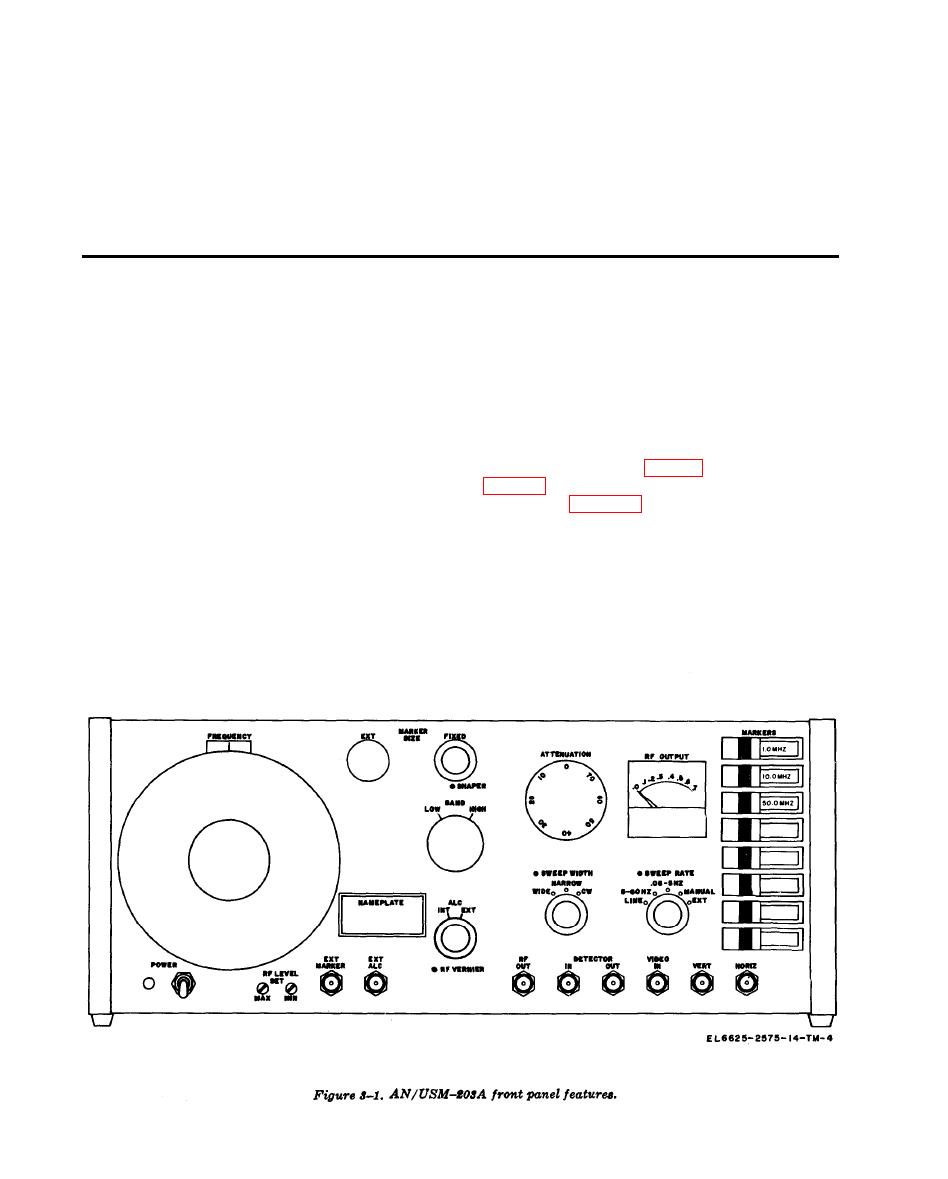
Section I. CONTROLS AND INSTRUMENTS
internally for 115 volts, and is con-
nected to a 230-volt line. A yellow label
Observe the following cautions to avoid damage
attached to the power cord near the
to the equipment.
plug indicates 115 volts. A red label
CAUTION
indicates 230 volts.
The following combinations of switch
settings and open connectors can dam-
age the rf section of the AN/USM-
203A.
POWER Switch set to ON.
BAND switch set to HIGH.
tabulated in table 3-1.
EXT ALC connector not coupled to
b. Internal switch S102 is located on the main
external monitor.
printed circuit board and normally is shipped
ALC switch set to EXT.
in the video blanking position. The switch may
-
CAUTION
be set to rf blanking so that the B+ to the rf
The AN/USM-203A can be operated at
oscillator and video amplifier are turned off dur-
either 115 volts, 50/60 Hz, single phase,
ing. the sweep display retrace. This control is not
or 230 volts, 50/60 Hz, single phase.
available to the operator, and its setting shall be
-
Damage will result if the unit is wired
determined at the time of calibration.

