Section IV
Paragraphs 4-60 to 4-64
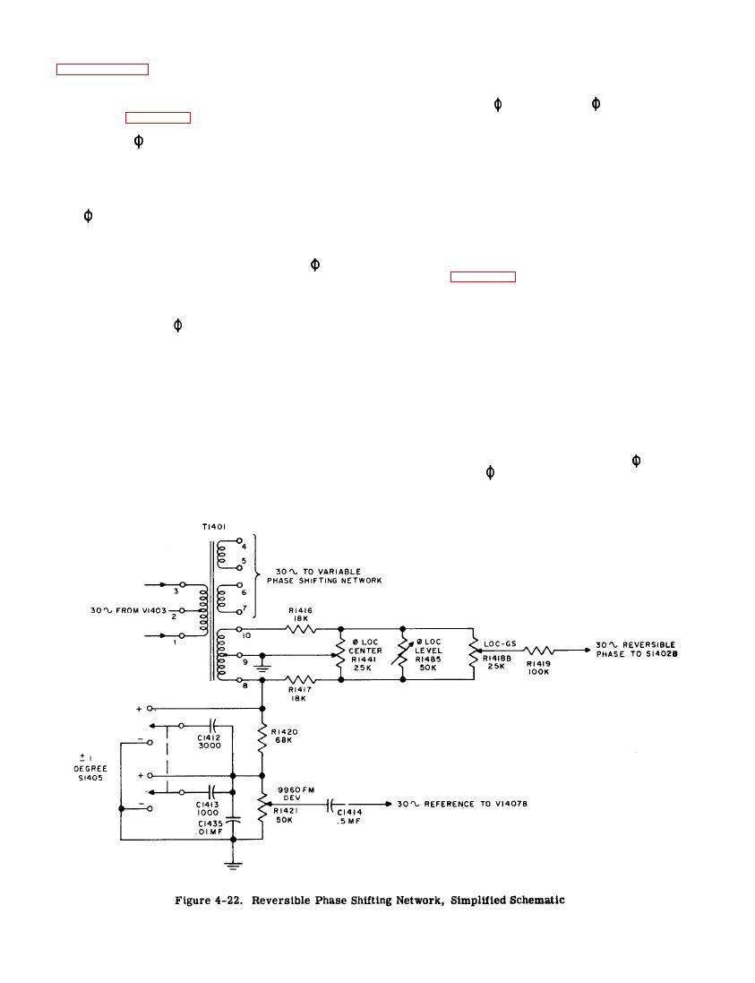
LOC, 30~ VAR
and 9960 FM
4-62. During VOR,
operation a 30-cps reference signal is taken from
(See figure 4-22.)
terminal 8 on T1401 for frequency modulating the 9960
cps oscillator. This reference signal may be shifted
4-61. During
LOC operation the 30-cps signal may
in phase one degree by changing the circuit constants
be in phase with the 30-cps reference signal that fre-
with 1 DEGREE switch S1405. This allows a one de-
quency modulates the 9960 cps oscillator or 180 out
gree increment to be placed on any azimuth selected
of phase with this reference signal. This is accom-
on the VOR switch. The reference signal appears
plished by using a center-tapped secondary of T1401
across 9960 FM DEV control R1421 which controls the
with the center tap grounded. Resistors R1416, R1417
amount of frequency deviation of the 9960 cps oscil-
and
LOC CENTER control R1441 are connected
lator. It is coupled through C1414 to frequency modu-
across the secondary of T1401 forming a bridge cir-
lator V1407B.
cuit. The movable arm of R1441 is also grounded and
the signal on one side of R 1441 is 180 out of phase
4-63. 90 CPS AND 150 CPS CIRCUITS.
with the signal on the other side of ground.
LOC
LEVEL control R1485 in parallel with R1441 allows
(See figure 4-23.)
for setting the limit of the percentage of modulation
4-64. During TONE LOC, GLIDE SLOPE, 90~ and
as adjusted by LOC-GS control R1416B. LOC-GS con-
150~ operation, 90 cps and/or 150 cps is used to
trol R1418B selects the phase and amplitude of the
modulate the r-f carrier instead of 9960 cps frequency
30-cps signal during
LOC operation. With LOC-GS
modulated at 30 cps. A 30- cps signal of considerable
control R1418B set to its midposition (middle of the
amplitude is taken from 30 cps amplifier V1403 and is
white center segment on the front panel) there is no
applied across saturable reactor L1401, a small audio
30-cps output from this circuit. As the LOC-GS con-
reactor whose core is insufficiently large for the level
trol is turned off center, a 30-cps signal in phase or
involved and consequently saturates. This saturation
180 out of phase with the reference signal is fed
causes the signal appearing across R1430 to be dis-
through isolating resistor R1419 to AUDIO SELECTOR
switch section S1402B. The phase of this signal de-
torted and very rich in harmonics. Capacitor C1422C
pends on the direction of rotation of the LOC-GS con-
places the bottom of R1430 at a-f ground and acts as
trol and its amplitude depends on how far off center
a d-c blocking capacitor f or the plate voltage of V1403.
AUDIO SELECTOR switch section S1402E disconnects
the control is turned. With the LOC-GS control set to
the top line of either the right or left segment, this
the ground from the input circuit on VOR,
LOC,
signal should modulate the carrier 11.5 percent; on the
1000 ~, 30 ~ VAR
and 9960 FM, thus disabling the
bottom line the percentage modulation is 14 percent.
circuit.


