TM 11-6625-3025-14/ET426-AA-MMA-010/E154 VII210/T.O. 33A1-8-902-1-1
(4) Set the oscilloscope sweep rate. Connect oscilloscope external sync connector to the V drive source.
Set oscilloscope channel 1 input amplitude sensitivity at 0.5v per division.
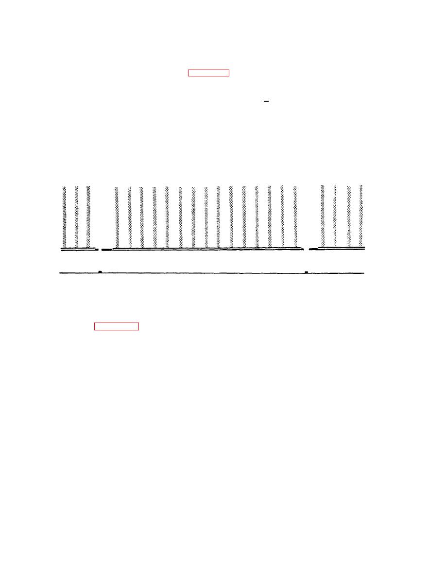
(5) Compare oscilloscope display to figure 6-17.
(6) Observe the video portion of the signal while turning the VIDEO LEVEL control from 0 to 10. Video
amplitude should vary from 0v. to 1.0v peak-to-peak +0.10v. The sync and blanking portions of the
composite video signal should remain at the levels set in flat field.
(7) Connect the video output connector to the monitor input to display the dot pattern. Check that dots
occur at the intersection of the H bar and V bar elements of the bar pattern. The white dots are
displayed on a black background for the WHITE pattern mode, and the black dots are displayed on a
white background for the BLACK pattern mode.
(8) Performance verification of the dot function is now complete.
Figure 6-17. Oscilloscope Display of the DOT Signal Waveform at Vertical Rate, White Polarity
6-41. H Stripe, V Stripe, and Window Adjustments. These patterns are related and are derived from common
horizontal and vertical elements. Therefore adjustment is considered for these patterns as a group. The circuit cards
involved include (see figure FO-21):
H Window. ..............................................................................................Position 3B
V Window ...............................................................................................Position 4B
Polarity .................................................................................................. Position 3C
6-46

