TM 11-6625-3041-12/TO 33A1-8-908-1
1-14. EQUIPMENT DATA (cont)
Input/Output All inputs and outputs can be connected to one another without
damage and are protected against short circuits and open cir-
Protection
cuits. NRZ inputs and outputs are protected against dc over-
voltage of 5 V from line-to-ground. Diphase inputs and out-
puts are protected against overvoltages of 56 V from line-to-
ground, and transients from line-to-ground of +1 kV for 10 s
and +350 V for 2 ms.
Error
Total Errors: 7-digit display indicates total errors detected,
Indications
can be reset to zero by RESET DISPLAY pushbutton.
Bit Error Rate (BER): Three indicators:
NO GO l . . . . BER equal to or greater than 1 error per 1000 bits
(10-3).
MARGINAL . . BER less than 1 error per 1000 (103) and equal to
or greater than 1 error per 100,000 (10-5).
5
GO . . . . . . . . BER less than 1 error per 100,000 (10- ).
Alarms
Power Supply: POWER SUPPLY indicator lights when built-in
test equipment detects a fault on a power supply card.
Logic: FAULT indicator lights when built-in test equipment
detects a fault on a power supply card or a logic card.
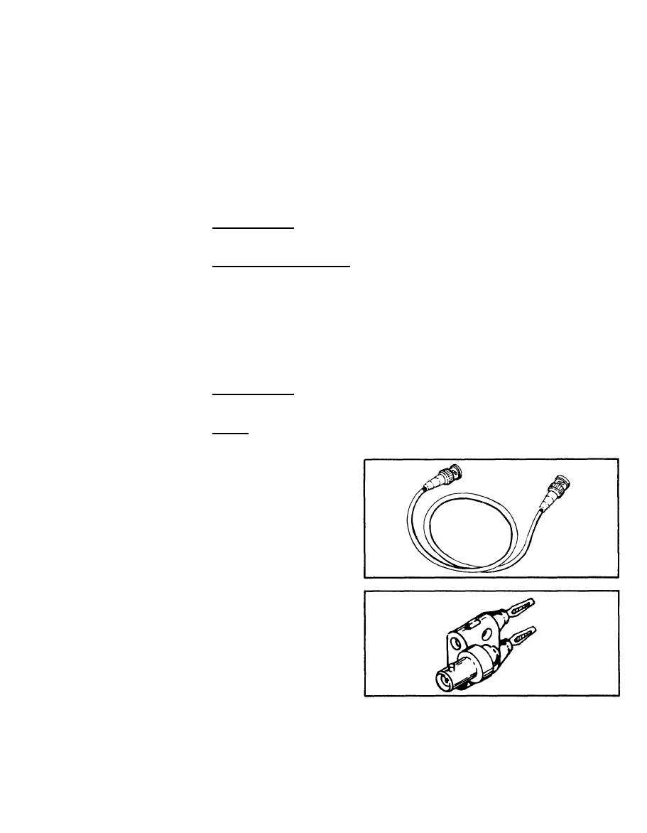
Four 4-foot cables
BNC Cables
with BNC connector
on each end are
supplied in the
front cover.
Four double-banana
BNC
plug-to-BNC adapt-
Adapters
ers are supplied
in the cover.


