TM 11-6625-3051-12
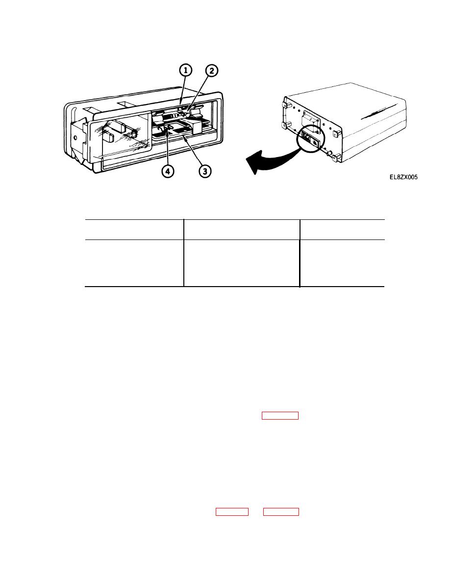
Table 2-3. Voltage Card Position and Fuses
Input Voltage
Card Position
Fuse
90 to 105
100
1/2 amp
108 to 126
120
1/2 amp
198 to 231
220
1/4 amp
216 to 252
240
1/4 amp
b.
Check fuse (2) to see if it is missing, broken, or appears to be blown. If fuse is missing, broken or
appears to be blown, contact next higher level of maintenance.
2-5. OPERATING PROCEDURES.
The following procedures cover Signal Generator SG-1171/U front and rear panel controls and connectors. Data
is given to help you to operate the equipment in each of the five modes described in Chapter 1, Section Ill.
a.
be repeated cycle after cycle. Each waveform can be modulated with either external or internal signals. Both
internal and external modulation can be from amplitude, frequency, or phase sources. Only one of the many
outputs possible in this mode will be produced in the following steps.
(1)
Set POWER OFF/ON switch (1) to OFF. (Refer to figure 2-1)
(2)
Connect a 50 ohm BNC to BNC coaxial cable from the FUNCTION OUT (50 Ω) connector (14).
(3)
Terminate remaining end with a 50 ohm feedthrough load.
(4)
Connect terminated end of BNC cable to test equipment.
Set POWER OFF/ON switch (1) to ON.
(5)
Set all controls to positions given in table 2-4. Use figure 2-1 to locate the desired controls and/or
(6)
connectors.
2-7


