TM 11-6625-586-45
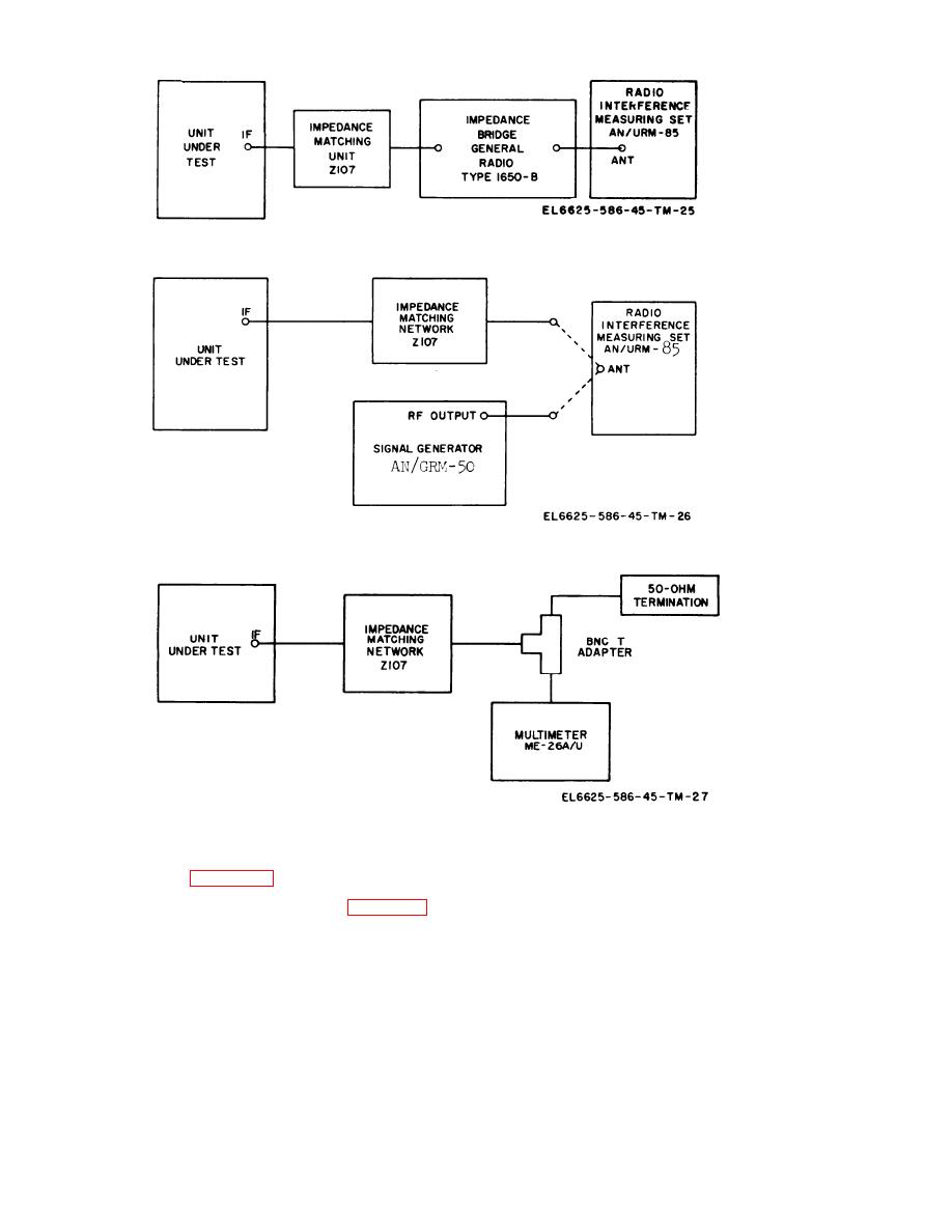
Figure 5-2. IF output impedance, test setup.
Figure 5-3. IF output level (10 UV), test setup.
Figure 5-4, IF spurious outputs, test connections.
g. Connect unit under test and the test equip-
NOTE
ment as shown in figure 5-5.
given in steps k t h r o u g h n b e l o w
The procedure
describes how
to obtain the lowest possible dis-
tortion at the
correct frequency with maximum
and with the specified switch settings, check that
output voltage
at E29.
the deviation and distortion readings are within
k. Adjust 150 HZ ADJ R16 for 150 Hz indi-
limits. If distortion readings are out of limits,
cation on electronic counter.
proceed with step i to adjust. If deviation read-
ings are out of limits, proceed to step q to adjust.
l. Check audio distortion at E29. It should be
less than 0.4%. If distortion is greater than 0.4%,
i. Connect distortion analyzer to E29 on audio
slowly turn AUDIO DIST ADJ R15 counter-
board. Connect oscilloscope and electronic counter
clockwise for 0.4% distortion indication.
to INT MOD OUT.
m. Again check for 150 Hz indication on elec-
j. T u r n F U N C T I O N s w i t c h t o 1 5 0 H Z a n d
tronic counter. If frequency is off, very carefully
DEVIATION control fully clockwise.
adjust 150 HZ ADJ R16 for correct frequency.
5-8 Change 1


