TM 11-6625-586-45
ah. Repeat steps ae and af and record value of
attenuation as LL.
range.
ai. Perform the following calculation for the
as. On attenuator calibrator, turn reference
output voltage when 80 db attenuation is in-
attenuator knob until NULL meter reads zero;
serted.
set AFC switch to OFF position.
V L = VH (1 x 10⁻⁴)
where: VL and VH are in volts. (VH from step a b )
AFCDEV meter reads zero.
and (1 x 10⁻⁴) is loss factor far -80 db.
au. On attenuator calibrator, turn AFC switch
to ON position. Adjust VIDEO SET for set point
Note.
3KUV = -37.4 dbm
reading on VIDEO LEVEL meter.
.3UV = 117.4 dbm
-117.4- (-37.4) = - 8 0
N U L L meter on attenuator calibrator. Keep
aj. Calculate measured db change between set-
NULL meter on high sensitivity range by de-
tings 3KUV and .3UV on LO RF UV dial.
creasing reading on attenuation counters by turn-
L = LH LL
ing reference attenuator knob.
where: L = db change from 3KUV to .3UV set-
for peak reading on NULL meter of attenuator
tings on dial.
calibrator. Keep NULL meter on high sensitivity
LH from step af.
range as stated in step av.
LL from step ah.
ax. Turn power off on AN/URM103 test os-
cillator.
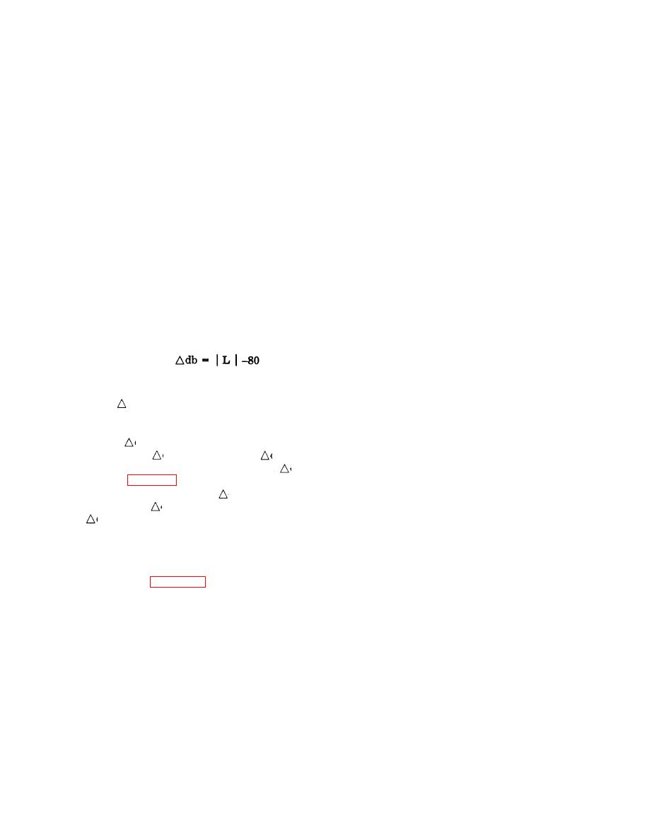
the difference between theoretical value of loss
ay. Repeat steps s (10) and s (11).
(80 db) and actual measured value of loss.
az. Turn AN/URM103 and test oscillator to
power on.
where: L = measured value of attenuation in db
ba. Repeat step s (13).
from step aj.
bb. Repeat steps as through aw.
al. If
db = 0, record output voltage as value
bc. Repeat steps s (16) through s (21) and re-
of VL of step ai and proceed to step ao (multiply-
cord reference A, reference B, and reference C
ing factor = 1).
for 50 MHz readings and calculations.
am. If
db is positive, attenuation is greater
bd. Repeat steps u through y.
than 80 db and
db is a loss; and if
db is nega-
be. Repeat. steps u through y for values on LO
tive, attenuation is less than 80 db and
db is a
RF UV dial of 100, 30, 10 and 3 UV and record
gain. From table 53 determine multiplying fac-
under 50 MHz.
tor for calculated value of
db. Remember use
bf. Repeat step z except use 1KUV setting.
loss column if
db is positive, and gain column
bg. Repeat steps aa and ab.
if
db is negative.
an. Calculate output voltage record.
set up as shown in figure 3lc.
V = VL x (Multiplying factor)
where: VL and V are in volts.
bi. Repeat steps ad through af.
ao. Disconnect test set-up and connect test set-
bj. On AN/URM-103 turn LO RF UV dial
up as shown in figure 5lC.
such that lUV is under indicator line.
bk. Repeat steps ae and af and record value of
and RF TUNING such that output frequency is
attenuation as LL.
50 MHz. Place LO RF UV dial such that 10KUV
bl. Repeat steps ai through an except in step
is under indicator line. Turn RF SET TO LINE
ai use loss factor of (1 x 10⁻³) for 60 db. Calcula-
control such that RF meter reads on "red line."
tions in this case determine the voltage output
All other controls remain as is.
with LO RF UV dial at lUV and RF meter set at
aq. Set controls an test oscillator as follows:
"red line", and output frequency of 50 MHz. The
Attenuator dial
+5 dbm position
procedure is the same as for 30 MHz except meas-
BAND SWITCH C
ured db step is from lKUV 60 db, instead of a
TUNING
80 MHz
80 db step as in the 30 MHz case.
OUTPUT LEVEL adjust for set level
mark on OUTPUT
and RF TUNING dial such that output frequency
meter
SELECTOR
is 80 MHz.
CW position
5-5


