TM 11-6625-586-45
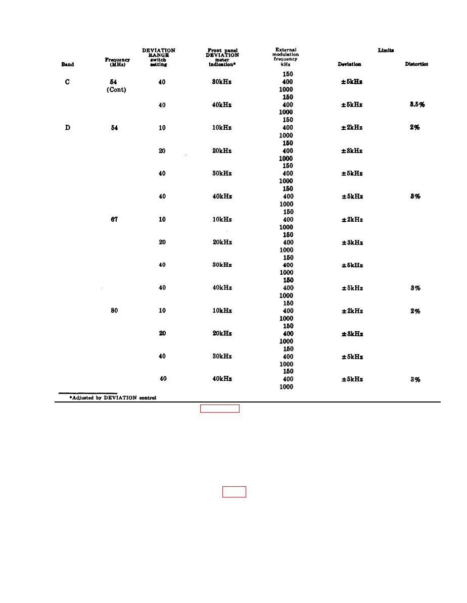
Table 6-3. Internal Modulation Deviation and Distortion Check Continued.
quency. Adjust level of this signal to obtain full-
and with the specified switch settings, check that
scale deviation of 10 kHz as read on DEVIA-
the deviation and distortion are within limits.
TION meter. Record the amplitude of this signal
g. Turn DEVIATION RANGE switch to 40.
for future reference.
h. Adjust the DEVIATION control fully
clockwise.
modulating signal from 100 Hz to 30 kHz ad-
i. At frequencies of 20 and 80 MHz, measure
justing the voltage level when necessary to ob-
the external modulating voltage required to ob-
tain 10kHz deviation. Observe and record the
tain a full scale reading on DEVIATION meter
maximum and minimum voltage levels.
at modulating frequencies of 10 and 30 kHz. Ta-
n. For external modulating frequencies of 100
ble 6-5 gives the specified limits.
to 15000 Hz, the voltage required to give 10 kHz
j. Turn DEVIATION RANGE switch to 10,
deviation should be within 10 percent of the
and adjust DEVIATION control fully clockwise.
voltage measured in step l. For external modu-
k. Set unit under test to produce output fre-
lating frequencies above 1500 Hz, the voltage
quency of 20 MHz.
required to give 10 kHz deviation should be with-
l. Apply a 1 kHz external modulating fre-
in 20 percent of the voltage measured in step l.
6-5


