
TM 11-6625-1559-12
fer to paragraph 3-5b through e for the correct
(3) Perform the procedure in paragraph 3-
6d through 1, to obtain the best display on the
procedure for using external markers.
oscilloscope screen.
(4) Keep the setting of the RF OUTPUT
Receiver
control as high as possible without causing dis-
tortion, but keep at least 10 db of attenuation
on the ATTENUATOR db control to provide a
a. Bandpass Measurement. The response curve
proper impedance match to the input of the re-
of the RF portion only of a receiver may be
ceiver.
analyzed by following the procedures in (1)
through (6) below.
(5) Observe the pattern on the oscilloscope
screen; make adjustments and measurements as
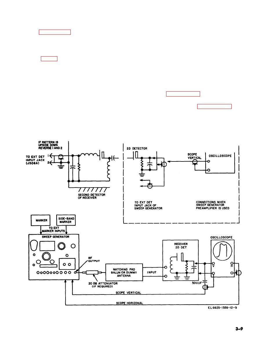
(1) Connect the RF OUTPUT jack of the
described in paragraph 3-5.
sweep generator to the input terminals of the
receiver through a matching pad; balun, or dum-
(6) If the response curve has sharp changes,
my antenna, as required.
perform the procedure in paragraph 3-6n, o,
and p.
(2) Connect a suitably shielded output ca-
ble from the EXT DET jack to the dc load re-
b. Eliminate of Hum. If the forward and re-
sistor of the receiver mixer. (This connection
turn traces cannot be brought into coincidence
may be a test point on the receiver.)
when phasing is attempted, the trouble is proba-
Figure 3-4. Setup for testing complete receiver.

