
TM 11-6625-1559-12
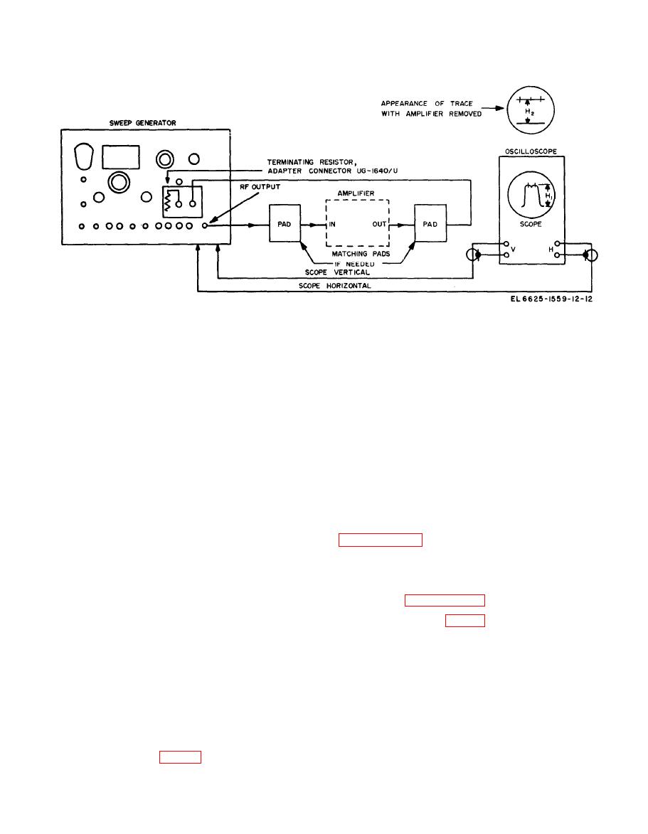
(1) Connect the RF OUTPUT jack through
(6) Reconnect the amplifier input and out-
a test cable to the grid of the tube preceding
put terminals to the test cables. Do not make
the stage to be tested, in series with a 10-uuf
any adjustments, even if the oscilloscope pattern
capacitor. Keep the connections as short as possi-
leaves the screen.
ble.
(7) Adjust the ATTENUATOR db control
(2) Insert a 6- to 10-db attenuator in the
on the sweep generator clockwise until the re-
test cable for a better response curve presenta-
sponse curve on the oscilloscope screen returns
tion.
to a point slightly higher than the position
noted in (5) above.
(3) Connect the output of the stage to be
tested through a 10-uuf capacitor and a test
(8) Adjust the RF OUTPUT control on the
cable to one DETECTOR jack on the sweep
sweep generator counterclockwise until the re-
generator, Terminate the other DETECTOR jack
sponse curve height is exactly at the position
with Adapter-Conneotor UG-1640/U.
noted in (5) above.
(4) Perform the procedure described in
(9) The decibel gain of the amplifier under
test is determined by the combined readings of
display on the oscilloscope screen.
the ATTENUATOR db dial and the DBM read-
ing on the VOLTS meter. For example, if the
(5) Observe the pattern on the oscilloscope
ATTENUATOR db dial is on 30 and the VOLTS
screen; make adjustments and measurements as
meter reads -6DBM, the amplifier gain is 36
described in paragraph 3-5.
decibels.
if the individual stage to be tested is part of a
feedback circuit involving other stages. This
The sweep generator may be used to test an
method requires the use of a broadband amplifier
individual stage in an amplifier. To do this,
with a response that is flat beyond the frequency
connections to the input and output circuits of
limits of the particular stage to be tested. Make
the individual stage must be made by a method
measurements as follows:
that does not affect its frequency response. Two
methods of making this connection are described
(1) Connect the RF OUTPUT jack of the
below. The choice of method depends upon the
sweep generator through a test cable to the out-
circuitry of the amplifier to be tested.
put of the stage preceding the one being tested.
Use a series capacitor small enough to have
to the individual stage directly. Perform the fol-
negligible loading effect on the circuit but large
lowing procedure.
enough to give an adequate response curve dis-

