
TM 11-6625-2575-14
the test setup in figure 7-12, but make the fol-
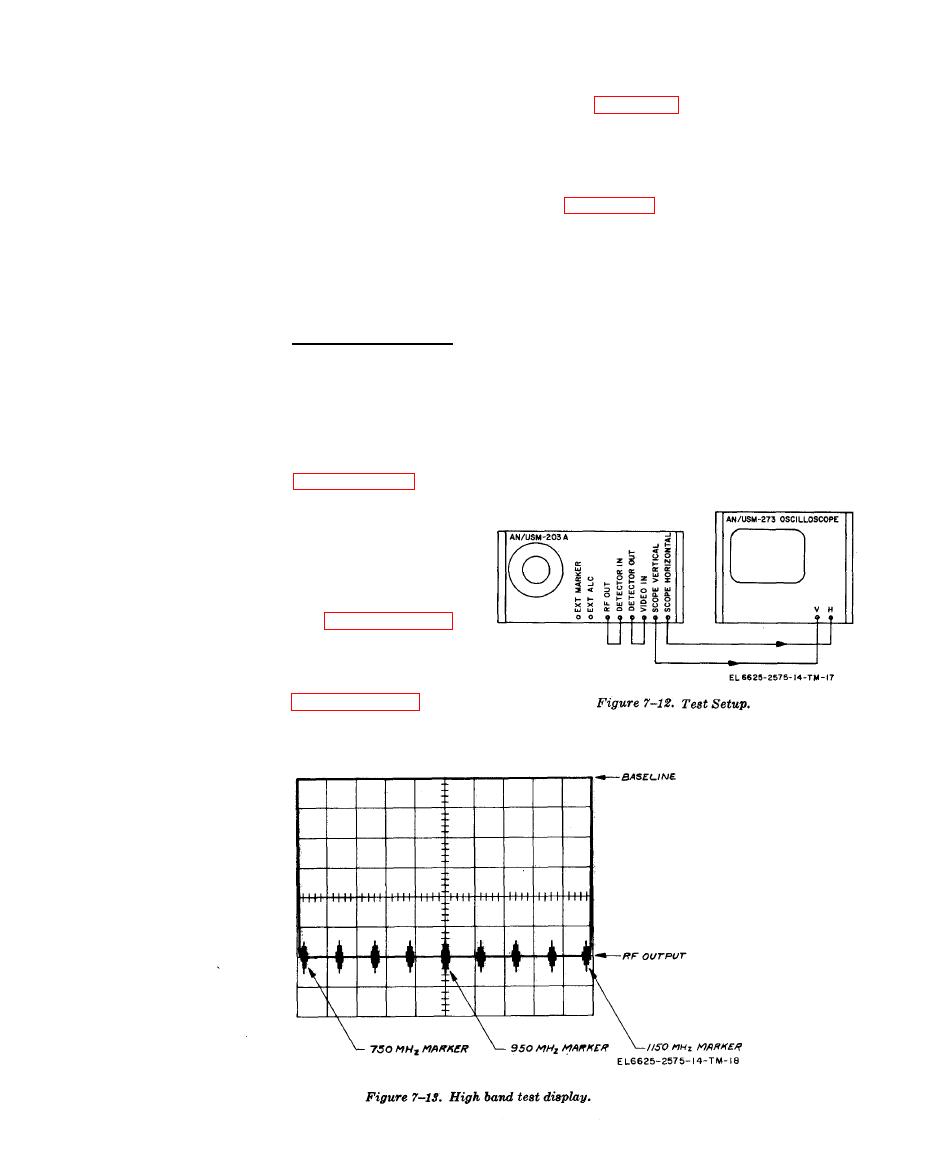
(2) Set the display oscilloscope as in e
lowing front panel control changes.
above, except adjust the horizontal display so
that the 750-MHz marker and the 1150-MHz
a. Test the unit in the 5-60 Hz, the .05-5 Hz,
marker are spaced 8 centimeters apart.
and the MANUAL positions of SWEEP RATE.
(3) Align the end markers with the vertical
The display shall trace a counterclockwise pat-
graticule lines in the display.
tern as in figure 7-13, except at a rate depending
on the SWEEP RATE vernier setting.
(4) Observe the oscilloscope display and de-
termine which marker deviates farthest from its
b. Test the unit in the NARROW SWEEP
respective graticule line.
WIDTH position. Proceed as follows.
(5) The sweep linearity may be obtained
(1) Set SWEEP WIDTH switch to NAR-
from the following equation:
ROW.
(2) Set the 1.0 MHz MARKER to ON.
NON-LINEARITY (%) = MAX DEV MHz X 100
(3) Set the 50.0 MHz MARKER to ON.
400 MHz
(4) Set SWEEP RATE switch to LINE.
The nonlinearity shall not exceed 5 percent
(5%).
(5) Set other controls as in paragraph 7-
10.
k. Evaluation of performance follows:
(6) Observe the oscilloscope display.
(1) If the unit under test conforms closely
to the requirements and typical displays in a
through i above, proceed to paragraph 7-11.
(2) If the displays are obviously distorted,
or no displays appear, check a through i above.
If necessary, repeat the troubleshooting proced-
ure in Section III.
(3) If the displays and the test results are
marginal or are slightly out of tolerance, proceed
to the alignment procedure in paragraph 7-12.
After alignment, repeat the test procedures.
Use the test procedure in paragraph 7-10 and

