
TM 11-6625-2575-14
(7) Adjust the SWEEP WIDTH vernier to
(6) Set the 50 MHz MARKER to ON.
present a sweep width of approximately 10 MHz
(7) An expanded marker will be displayed
by observing the displayed markers.
along the horizontal display at each 50-MHz in-
(8) Adjust the CENTER FREQUENCY
terval.
dial over the HIGH BAND.
(8) A notch or zero-beat will be observed
(9) Center each 50 MHz marker, and ob-
when the CENTER FREQUENCY DIAL is ro-
serve the 50-MHz dial graduations. Each 50-
tated slowly.
MHz marker when centered in the display shall
(9) Observe the notches in the display and
be aligned within 1 division (10 MHz) of
the 50-MHz dial graduations. The notches, when
each dial graduation of 50 MHz.
centered in the display, shall be aligned within
1 division (10 MHz) of each 50-MHZ dial
NOTE
graduation.
As frequency is decreased, the sweep
d. Check the rf output for 0.5-volt rms mini-
width decreases, and the displayed
mum output at the fully clockwise position of
marker amplitudes increase. Adjust the
the RF VERNIER. Observe the RF OUTPUT
S W E E P WIDTH vernier and the
meter and the display amplitude. The amplitude
FIXED MARKER SIZE controls to ob-
shall be 0.53 volt minimum.
tain the required display.
e. Test the SWEEP WIDTH for maximum
c. Test the unit in the cw mode. Proceed as
and minimum sweep widths using the three in-
follows.
ternal markers.
(1) Set the SWEEP WIDTH switch to CW.
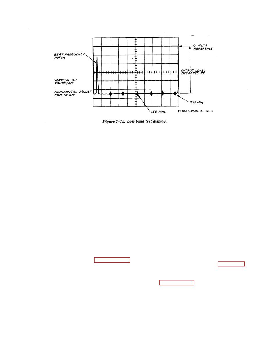
f. Test the unit in the LOW BAND position
(2) Set all MARKERS to OFF.
and at maximum SWEEP width. The scope dis-
(3) Set other controls as in paragraph 7-
play shall be typically as shown in figure 7-14.
10.
(4) Observe the oscilloscope display.
g. Make tests in a through f above for LOW
BAND performance. Units meeting all require-
(5) A horizontal line approximately 0.6 volt
ments in paragraphs 7-10 and 7-11 are ready for
below the top horizontal graticule line shall be
use.
displayed.
Section V. ALIGNMENT AND ADJUSTMENT PROCEDURES
The following procedures should be undertaken only if required to improve unit performance specified
in section IV.

