
TM
11-6625-3041-30/TO
33A1-8-908-12
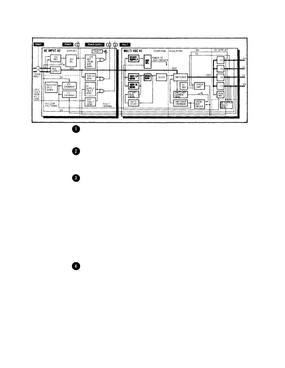
1-24. MULTI VDC (A1) START
Start
At turn on, the 150V Supply output at J2-21 begins to rise
Supply
towards +150V. When it reaches 15 to 25V, VR1 in the Start Sup-
ply conducts and produces a +10V Ref output at its cathode.
The +10V Ref voltage turns on Q1, which produces a +9V out-
put at its emitter. Because there is yet no +12V Run Ref input
at CR4 anode, the +9V Start Ref voltage is used as the Ref Power
voltage and powers the Sens, Sens Sum, and Clock circuits.
The negative input to the 150V Hi Sens at U5-4 is derived
150V Hi
from voltage divider R29-R63-R65 and is 1/20 the voltage applied
Sens
at the top. The applied voltage is from the 150V Supply so that
the negative input at U5-4 would normally rest at 1/20 x 150V =
7.5V. But the 150V Supply at this time is well under 150V, so
the negative input at U5-4 is only slightly over +1V.
The voltage at the positive input at U5-5 is derived from volt-
age director R71-R72 and is one-half the voltage applied at
the top. The applied voltage is the Ref Power which, at this
time, is the +10V Ref voltage so that the voltage at U5-5 is
1/2 x 10V = 5V. Therefore, the voltage at the positive input is
more positive than that at the negative input. The positive
input takes control and sets the output of the 150V Hi Sens at
U5-2 high.
150V Lo
The negative input to the 150V LO Sens at U5-8 is +5V,
Sens
which is more positive than the positive input at U5-9. The
negative input takes control and sets the output of the 150V
Lo Sens at U5-14 low.

