
TM 11-6625-3041-30/TO 33A1-8-908-12
2-6.
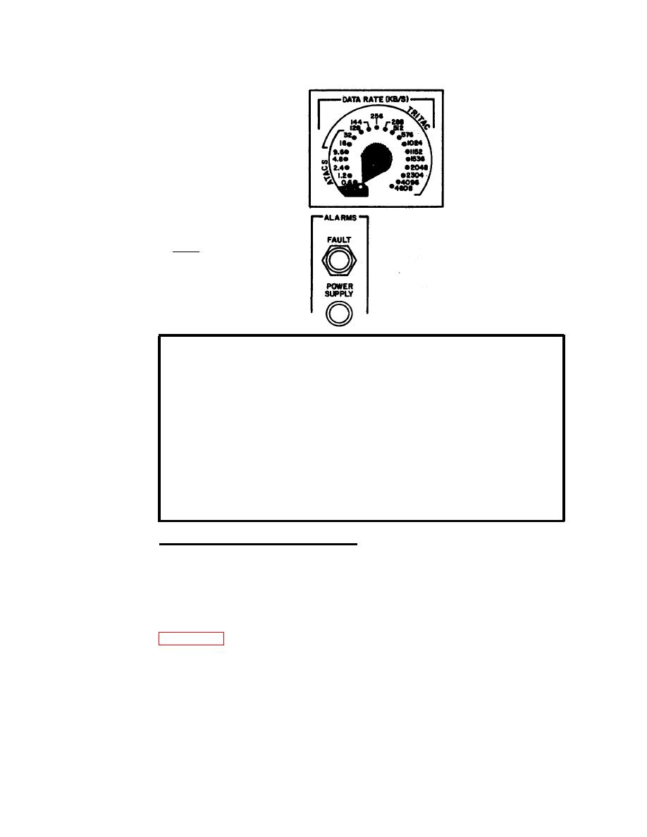
SG-1139 CHECK PROCEDURE (CONT)
q Set
controls as
Step Unbalanced
follows:
4
NRZ Out
POWER . . . . . . ON
TIMING . . . . MASTER
DATA RATE .. . 576
ATACS
Red FAULT alarm
indicator must
not be lit. If
it is not, pro-
ceed to step 5.
This step checks the following:
Multi VDC card . . . . +12V supply
Transmit 1 card . . . Master timing select
576 family data rate decode and select
Master Osc at 9.216 MHz
NRZ Clock Gen at 576 kHz
PR Gen
Single Error Inject
UNBALANCED TMG OUT circuits
UNBALANCED DATA OUT circuits
Transmit 2 card . . . Control Clock Gen
Control Filter . . . . TIMING control MASTER setting
DATA RATE control 576 family setting
If FAULT alarm indicator is lit:
Remove LOGIC access cover (refer to TM 11-6625-3041-12) and
note which card contains a lit fault indicator. Replace that
card and repeat step 4.
If replacement card does not provide proper indication,
possible cause is Control Filter A8. Replace (refer to
para 2-13), and repeat step 4
If no logic card contains a lit fault indicator, remove POWER
SUPPLY access cover (refer to TM 11-6625-3041-12) and note
Replace that card
which card contains a lit fault indicator.
and repeat step 4.

