
TM 11-6625-3051-12
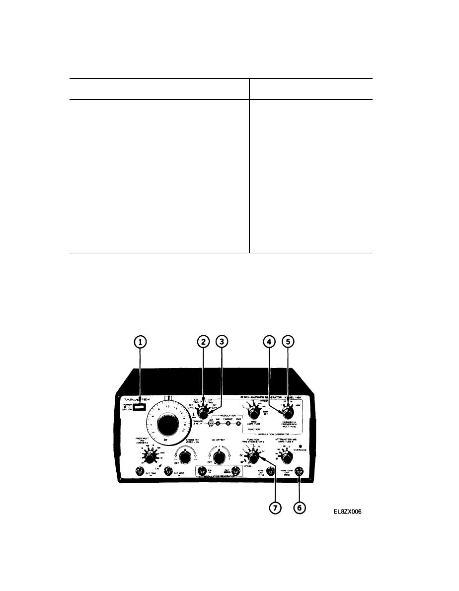
Table 2-4. Continuous Mode Control Setup Positions
Control
Position
Frequency Dial
1.0
FREQ MULT
1K
VERNIER
Clockwise
SYMMETRY
OFF detent
DC OFFSET
OFF detent
FUNCTION (lower switch row)
Square Wave
TRIG START/STOP
0CAL detent
0/20
AMPLITUDE (lower switch row)
Clockwise
Generator Mode (EXT GATE, etc)
CONT
TRIGGER LEVEL
Counterclockwise
MODULATION Switches
OFF
FUNCTION (Modulation Generator)
Sine Wave
MOD AMPLITUDE
Counterclockwise
FREQ/PERIOD MULT
10/1K
VARIABLE
Clockwise
(7)
Set FUNCTION switch (12) to produce desired waveform.
Internal Triggered Mode. Operation is basically the same as in the continuous mode with the exception
b.
that the signal generator will output a single cycle of the main frequency for each internal trigger. The internal
modulation generator can be varied to provide triggers at different intervals. Use the following steps to operate
the signal generator in the internal triggered mode.
2-8

