Section IV
Paragraphs 4-20 to 4-22
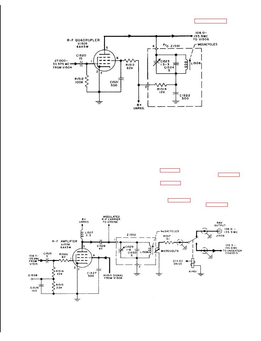
4 - 7 R-f Quadrupler V1505, Simplified Schematic
The audio signal from modulator V1508 is coupled di-
aligning the r-f chassis. The measured voltage is de-
rectly to the screen grid of V1506. The r-f carrier
veloped across R1515. Bypass capacitor C1526 by-
is therefore modulated by the audio signal due to the
passes rf around the voltmeter that is connected to
audio variations appearing on the screen grid. The
E1508 during r-f alignment.
amplified and modulated output appears across the
plate load L1507 and is coupled through C1528 to the
4-22. The modulated r-f signal developed across
output tuned circuit Z1502. A portion of the modulated
Z1502 is coupled to NAV OUTPUT jack J1406 during
carrier is fed to demodulator V1509 for calibration
NAV operation. During GS operation the modulated
and test purposes. Z1502 is tuned in 28 steps of one
r-f carrier is delivered to the univerter chassis.
megacycle each in the frequency range of 108.0 to
Coupling is accomplished through a piston type r-f
135.9 mc depending on the setting of the outer knob of
attenuator (figure 4-9) that is mounted in such a fash-
the MEGACYCLES control which varies the position
ion that a small single-turn pickup loop (4, figure 4-9)
of the tuning slug of L1508. The band pass of Z1502
may be moved with respect to the final output coil
is sufficiently wide to cover the megacycle spread of
L1508 (2, figure 4-9) to vary the coupling and thus the
V1501. Trimmer C1529 is used to adjust the tuned
r-f output. The motion of the piston and loop is pro-
circuit at the upper frequency limit.
duced by a rack and pinion drive mechanism controlled
by the calibrated MICROVOLTS control. An inspec-
4-21. Terminal stud E1508 in the control grid circuit
tion hole (5, figure 4-9) in the housing allows for
of V1506 is used as a voltage measuring point when
checking the position of the loop (6, figure 4-9).


