Section IV
Paragraphs 4-23 to 4-30
because it reduces the effective r-f output of the sig-
nal generator by one-half. Under these conditions,
the MICROVOLTS dial reads twice the actual r-f out-
put. For example, to set up a 2000-microvolt signal,
the MICROVOLTS dial must be set to 4000.
4-25. A-F AMPLIFIER V1507 AND MODULATOR
V1506,
(See figure 4-10.)
4-26. A-f amplifier V1507 receives one of nine audio
signals from the audio chassis as determined by the
audio chassis as determined by the setting of the
AUDIO SELECTOR switch. These audio signals are
as follows:
a. 30 cps variable phase and 9960 cps, frequency
modulated at 30 cps.
b. 30 cps reversible phase and 9960 cps, frequency
modulated at 30 cps.
c. 90 cps and 150 cps sine waves.
d. 1000 cps sine wave.
e. 30 cps reversible phase.
f. 9960 cps, frequency modulated at 30 cps.
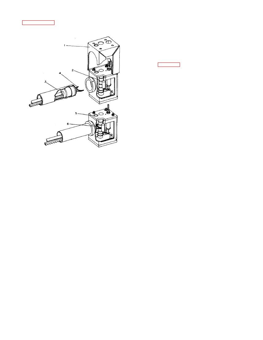
1
Shield can for Z1502 assembly
g. 90 cps sine wave.
2
Final r-f tank coil L1508
Attenuator removed from collar
3
h. 150 cps sine wave.
4
Pick up loop
5
Inspection hole
4-27. The selected audio signal is delivered to the
6
Point of normal 1/32 to 3/64 inch clearance
control grid of V1507 through an r-f filter (part of the
with MICROVOLTS set to maximum
filter assembly) that prevents rf from radiating on the
external leads of the r-f chassis. The audio signal is
amplified by V1507 and coupled through C 1543 to the
control grid of modulator V1508.
tial. The other end of the pickup loop- is connected
4-28. Modulator V1508 is a cathode follower used as
through impedance matching resistor R1517, located
a power amplifier to supply adequate drive to the
in the piston, to the r-f output cable. The output cable
screen grid of modulator V1505 with a minimum of
is in turn connected to the movable contact of coaxial
distortion to the audio signal. A fixed positive bias
relay K1401, located on the audio chassis. With the
is applied to the control grid by tapping off a voltage
NAV-GS switch in the NAV position, the r-f output is
divider, comprising R1528 and R1529, across the B+
connected to NAV OUTPUT jack J1406 which now has
supply. The output is taken from CARRIER SET con-
an output impedance of 53 ohms. With the NAV-GS
trol R1531 in the cathode circuit of V1508. This con-
switch in the GS position, K1401 is energized and the
trol adjusts the amplitude of audio signal that modu-
r-f attenuator output is connected to the univerter
lates the r-f carrier. A switch in series with the
chassis. The univerter chassis has unity gain with
movable arm of R 1531 allows the audio signal to be
the same output impedance as the r-f chassis. There-
disconnected from the output r-f amplifier.
fore, only the output frequency is changed during GS
operation.
4-29. DEMODULATOR V1509.
(See figure 4-11.)
for direct connection to receivers having an unbal-
anced input circuit of approximately 53 ohms imped-
output of r-f amplifier V1506 is coupled through C 1531
ance to match the output impedance of the signal gen-
to the grid of V1509A. This section of the demodu-
erator. Under these conditions, the MICROVOLTS
lator is an infinite impedance detector with a high in-
put impedance and a high fidelity output. This pre-
dial will be direct reading, For testing receivers
having a 95-ohm balanced input, Adapter UG-529/U is
vents loading of the r-f output circuit and gives a d-c
connected between the OUTPUT jack and the receiver
voltage output proportional to the input r-f voltage.
input, matching the impedance of the two units. The
This d-c voltage is coupled directly to V1509B which
adapter also has the effect of a 6-db attenuator pad
is connected as a cathode follower. The d-c output of


