Section VI
Paragraphs 6-6 to 6-10
f. If no tubes in the r-f chassis light and audio chas-
sis tubes are operating, check continuity of r-f filter
FREQUENCIES
assembly by connecting an ohmmeter between test
FREQUENCY-
CRYSTAL
point @ , its terminal 5, and test point
, terminal
INNER KNOB
IN KC
USED
3 on E1501. (E1501 is mounted on the fine frequency
POSITION
4875
Y1529
.0
4900
Y1530
6-7. CIRCUIT ISOLATION. After making a vacuum
1
4925
.2
Y1531
tube check on the r-f chassis, all tubes are found to
Y1532
4950
be good yet there is no r-f output, proceed as follows:
.3
Y1533
49'75
.4
5000
standoff
Y1534
a. Measure the voltage at test point
Y1535
5025
E1508 (figure 6-11), at the junction of R1515 and
.:
5050
Y1536
.7
R1516 with a d-c vacuum tube voltmeter having a
5075
Y1537
100, 000-ohm resistor in series with its probe. This
.8
5100
Y1538
.9
voltage should be greater than -1 volt over the entire
frequency range of the signal generator. If this volt-
age is present, check r-f amplifier V1506 and the out-
put circuit of the r-f chassis including 21502, r-f at-
tenuator, output coaxial cables and connectors, and
FREQUENCIES
coaxial relay K1401. If less than -1 volt is measured
FREQUENCY
CRYSTAL
, E1508, continue with step b below.
OUTER KNOB
at test point
IN KC
USED
POSITION
b. Connect the d-c vacuum tube voltmeter using a
7375.000
108
Y1501
100, 000-ohm resistor in series with its probe to the
7458.333
Y1502
control grid of each preceding stage and compare with
109
7541.66'7
Y1503
110
the following typical measurements:
7625.000
111
Y1504
7'708.333
112
Y1505
7791.667
TEST POINT
TUBE PIN
113
Y1506
D-C VOLTAGE
--
.
7875.000
114
Y1507
7958.333
1
Y1508
115
V1505
-30v
Y1509
116
8041.667
12. 5v
V1504
1
8125.000
117
Y1510
V1503
1
-2. 75v
8208.333
118
Y1511
8291.667
119
Y1512
8375.000
If proper drive is present on any of these tubes and
120
Y1513
there is little or no drive on the following stage, check
8458.333
121
Y1514
8541.667
122
the tube circuit for a defective component. If little or
Y1515
8625.000
123
no drive is measured on the grids of these tubes, the
Y1516
8708.333
Y1517
124
trouble is probably in the fine or coarse frequency
Y1518
8791.667
125
oscillator.
Y1519
8875.000
126
8958.333
127
Y1520
9041.667
128
Y1521
V1503 comes from both the fine and coarse frequency
Y1522
9125.000
129
oscillators. To check if the coarse frequency oscil-
lator is operating, detune T 1501 by inserting the brass
9208.333
Y1523
130
Y1524
9291.667
end of the tuning wand (1, figure 2-1) into L1511 (fig-
131
9375.000
Y1525
ure 6-11). If the coarse frequency oscillator is oper-
132
9458.333
ating satisfactorily a d-c vacuum tube voltmeter con-
133
Y1526
nected in series with a 100, 000-ohm resistor to pin 1
134
9541.667
Y1527
of V1503 will show a decrease in drive when T1501 is
9625.000
Y1528
135
detuned. If the coarse frequency oscillator is not op-
erating check V1502 and K1501 before removing the
oscillator. Relay K1501 may be checked by listening
carefully for a click each time the relay is energized
CHASSIS.
and de-energized by rotating the outer knob of MEGA-
CYCLES control. On even megacycle positions, K1501
should be energized and 21 volts dc will appear at test
sis is inoperative (no r-f output during GS operation)
, terminal 2 of the coarse frequency oscilla-
point
check all its tubes. With the signal generator removed
tor, Both the coarse and fine frequency oscillator
from its case, apply power to the signal generator and
may be checked by placing the antenna of a receiver
note whether all four tubes on the univerter chassis
near the lead on terminal 1 of either oscillator and
light. Because of the series-parallel arrangement of
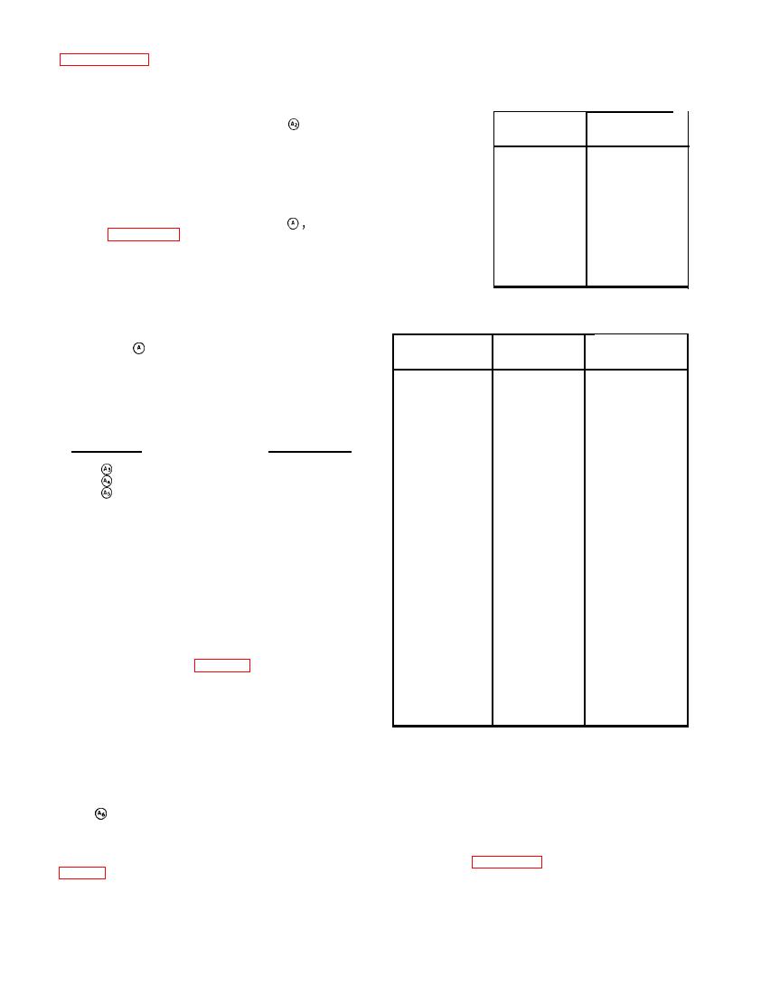
tuning the receiver to the oscillator frequency. Tables
tube filaments (figure 4-30) a burned out heater may
open the heater circuit for other tubes. Tube checking
tions of the MEGACYCLES control.
can be simplified by proceeding as follows:


