Section VI
Paragraphs 6-39 to 6-41
Generator SG-l/ARN. If sufficient SG-13/ARN output
within 0. 0065 percent. If any of the crystal frequen-
cannot be obtained, reset the stop on the attenuator
cies are found to be more than 0.0065 percent in error.
shaft (9, figure 6-10). With this stop set for a maxi-
it will usually be found that all the other frequencies
mum output of 200, 000 microvolt the attenuator dial
are in error in the same direction. A slight adjust-
will usually indicate that value with little error.
ment of C1534 at the bottom of the coarse frequency
oscillator should shift all the crystal frequencies so
that none will fall outside the 0. 0065 percent limits.
If any crystal still falls outside these limits insert a
Use extreme care in turning the attenuator dial
new crystal to obtain required frequency.
while the stop is being adjusted. If the dial is
turned too far, the U-shaped pick-up loop in
the attenuator may strike the final tank coil
and be damaged. This is usually evidenced by
a. Place all covers on the r-f chassis and tighten all
the CAR meter reading dropping to zero at the
cover screws securely. This is necessary to prevent
r-f leakage during alignment.
highest setting of the MICROVOLTS dial.
b. The r-f output is adjusted by comparing it with
the coil at the maximum setting of the MICROVOLTS
the output of a Signal Generator SG-l/ARN. Feed a
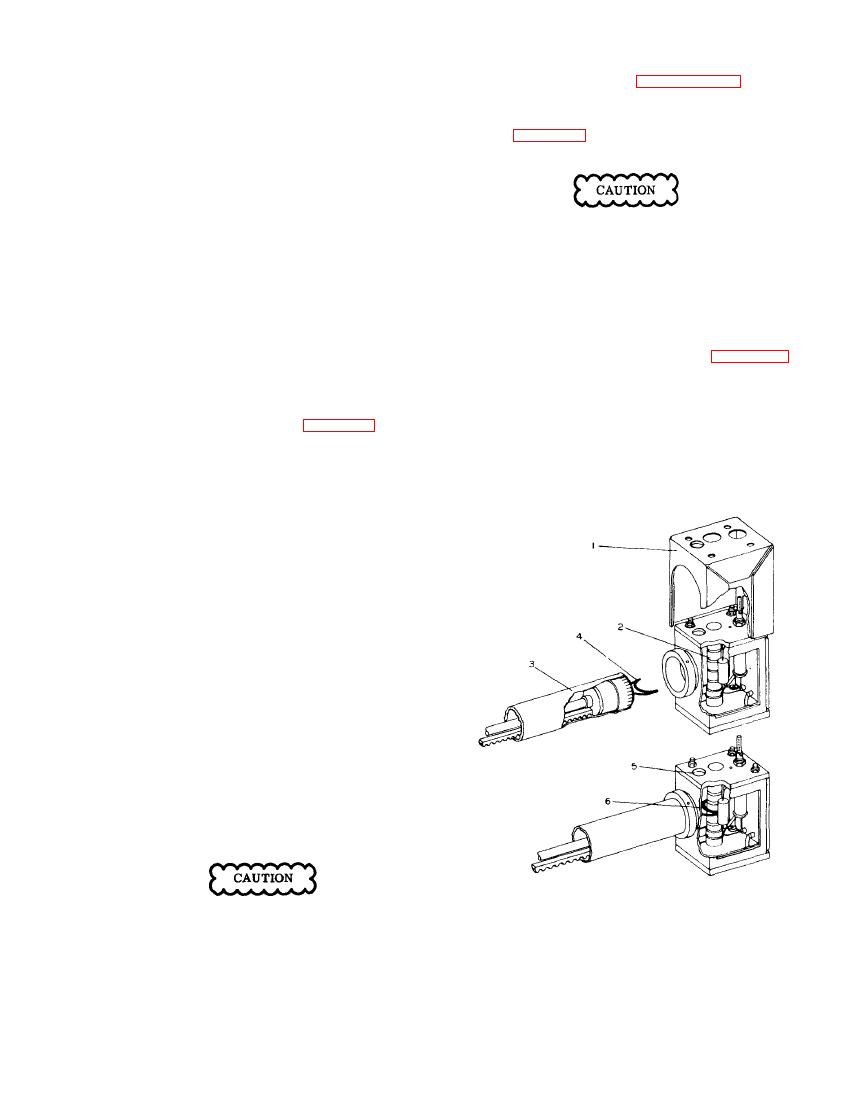
dial may be checked as follows. Refer to figure 6-13.
114.9 mc signal from Signal Generator SG-l/ARN in-
to an AN/ARN- 14 navigation receiver with a d-c
a. Remove the bottom r-f shield cover.
vacuum tube voltmeter connected to measure the re-
ceiver avc voltage. Use a 53-ohm 6-db pad in the
cable connecting the receiver to the SG-1/ARN to keep
b. Remove the four nuts and shakeproof washers on
the top of Z1502 and pull off the shield can (l).
the standing wave ratio low. See figure 5-1 for test
connections.
c. Shine a light through the hole (5) on top of the
housing and note the clearance (6) between the loop (4)
c. Set Signal Generator SG-l/ARN MICROVOLTS
dial to 500 microvolt and note avc voltage developed
in tbe receiver.
d. Substitute Signal Generator SG-13/ARN for the
SG-l/ARN using the same 6-db pad and adjust the
MICROVOLTS dial until the same avc voltage reading
is obtained. Adjust METER ZERO. The CARRIER
SET control should be adjusted to the red line prior to
this measurement. The MICROVOLTS dial should
read 1000. If not, loosen the dial set screws with the
Bristo wrench furnished and reset.
NOTE
.
The SG-l/ARN microvolt dial is calibrated
for use with a 6 db pad. The SG-13 micro-
volt dial is calibrated for a direct connec-
tion between NAV or GS output connectors
and receiver input.
A 53-ohm 6 db pad is used with the SG-13/ARN
output cable in this test only to insure proper
termination of the SG-13/ARN in case the re-
ceiver being used does not have exactly 53-
ohms input impedance. For this reason, the
SG-13/ARN MICROVOLTS dial must be set to
twice the reading of the SG-l/ARN microvolt
dial during this alignment procedure.
1
Shield can for Z1502 assembly
Take care to allow the signal from only one
2
Final r-f tank coil L1506
signal generator to get into the receiver while
3
Attenuator removed from collar
measuring the avc voltage. Adjust the signal
4
Pick-up loop
generator not in use to some other frequency
5
Inspection hole
while making measurements.
6
Point of normal 1/32 to 3/64 inch clearance
with MICROVOLTS set to maximum
e. Turn the SG-13/ARN MICROVOLTS dial to a max-
imum. This should give 200,000 microvolt which is
comparable to a 100,000 microvolt setting on Signal


