Section VI
u. The coarse frequency oscillator employs a fre-
q. Repeat steps o and p until the tuned circuits are
quency adjusting trimmer, C 1534 (figure 6-11), which
in resonance at both ends.
is adjusted at the factory and should not require any
further attention unless changes are made in the com-
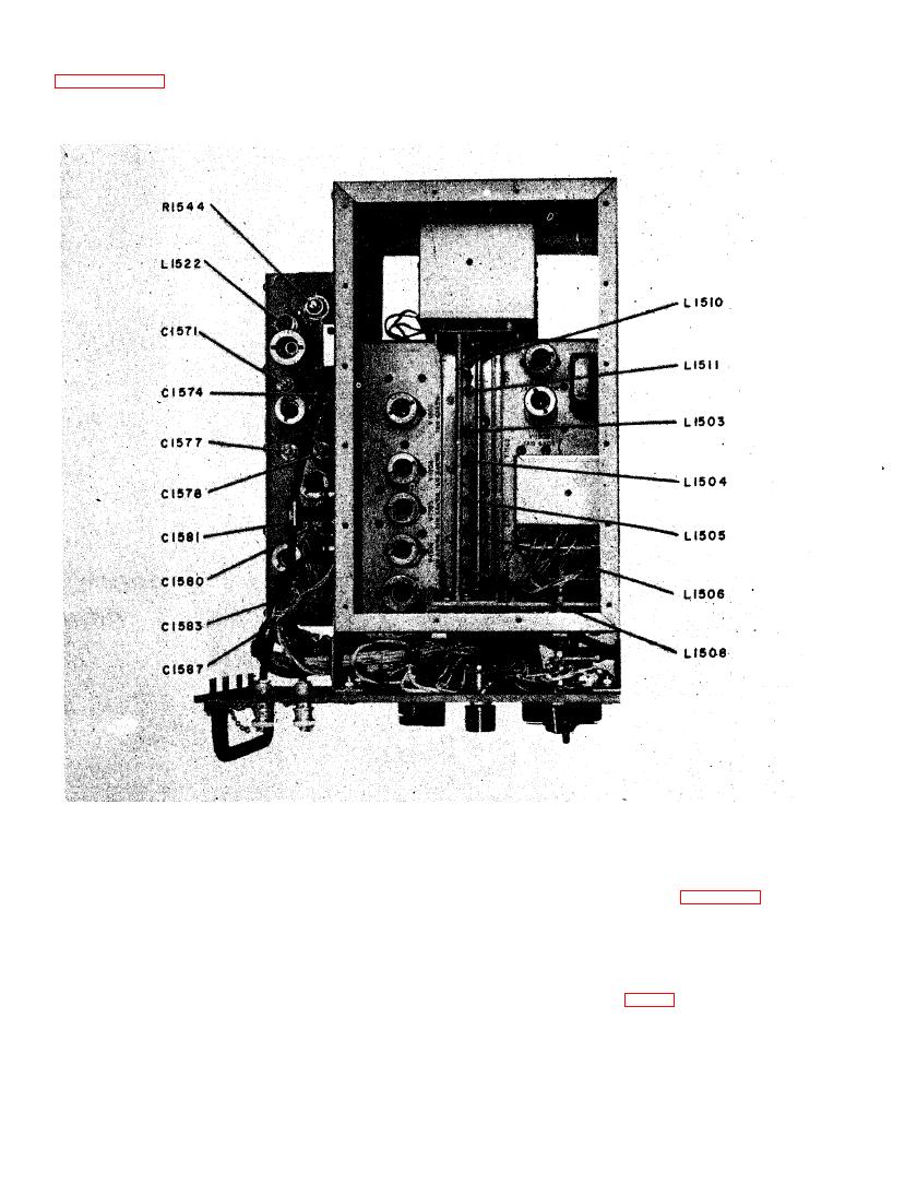
r. Adjust mixer coils in T1502 (L1503, L1504) by
ponents or wiring in the grid circuit of V1502. In this
tuning to 135.5 mc and inserting the iron end of the
event, measure the frequency of the oscillator using
tuning wand in one coil until the circuit is detuned
each of the 28 frequencies. Make these measurements
and the voltage on E1508 falls tO a low value Adjust
with a secondary frequency standard having an accu-
the trimmer on the other coil for maximum output.
racy of 0.001 percent. See table X for crystal fre-
Repeat this procedure for the other mixer coil.
quencies. A small pick-up loop inserted in the T1501
coil nearest the coarse frequency oscillator (L1510)
s. Tune to 108.5 mc and repeat procedure of step r.
will provide enough pick-up to permit measurement of
the 7375-9625-kc signals. Rotate the MEGACYCLES
t. Tune the coarse frequency oscillator output coils
control to each of the 28 positions and measure each
in T1501 (L1510, L1511) in the same manner as the
of the 28 crystal frequencies. All should be accurate
mixer (steps r and s above).


