TM
11-6625-3041-30/TO
33A1-8-908-12
1-20. LOGIC CARDS (A3, A4, A5, A6) INPUT AND FAULT SENSING
General
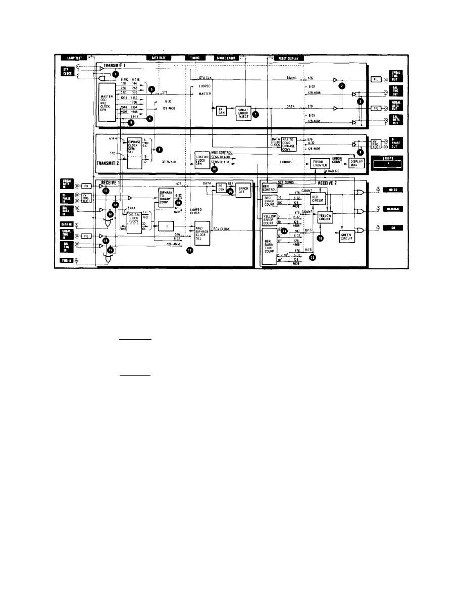
For general information refer to TM 11-6625-3041-12, Operator's
and Organizational Maintenance Manual. The SG-1139 includes
21 signal sensors. All are enabled regardless of the setting
of the TIMING control except sensor 1 Station Clock (enabled
in STA CLK mode only), and sensor 17 Looped Clock (enabled in
LOOPED Mode only).
Light On
Signal - Six sensors are input sensors. When an external input
With
signal is present, they light one (two for diphase inputs) of
the front panel indicators (STA CLOCK, DATA IN, and DATA OUT).
(table head)
No sig - Fifteen sensors are fault sensors. When an important
internal signal is not present, they light one of the card
fault indicators (A3, A4, A5, and A6).
Read
All sensors except two store activity and are read approximately
Interval
every 0.25 second (every 2 seconds on Receive 2 card). Whenever
(table head)
the signal they monitor disappears, it can be a 0.25 second or
2 seconds before the fault is indicated. When the signal
returns, it can be a 0.25 second or 2 seconds before the indi-
cation returns to a no-fault condition.
Two sensors are peak detectors and indicate a fault immediately
whenever the monitored signal drops below a preset level. When
the signal returns to normal, the indicator immediately returns
to a no-fault condition.
Data Rate
Many sensors are enabled only at certain settings of the DATA
RATE control such as sensor 3, which is enabled only from
(table head)
128 to 4608, etc.


