TM 11-6625-3041-30/TO 33A1-8-908-12
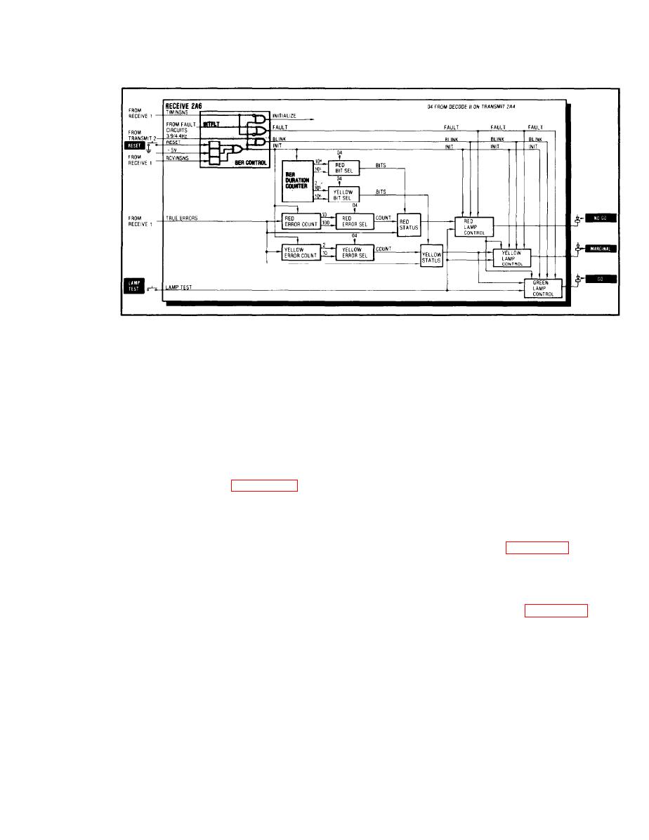
1-19. RECEIVE 2 (A6) BIT ERROR RATE
BER
The BER Control produces an Init output whenever the front
Control
panel RESET button is pressed (Reset output), when the unit is
first turned on (+5V input), or when the data and timing inputs
are first applied (Rcvinsns input). The Init output sets the
BER circuits to zero.
The BER Control produces an Initialize output whenever the
timing input is missing (Timinsns). The Initialize output is
used by the Transmit 2 card to set the Error Counter to zero.
The BER Control produces a Fault output whenever the timing
input is missing (Timinsns) or a fault is sensed (Intflt, refer
to para 1-20). The Fault output turns off all three BER
indicators.
The BER Control produces a blink output during the initializa-
tion period. The Init output allows the 3.9/4.4 Hz output from
the Control Clock Gen on the Transmit 2 card (para 1-18, Control
Clock Gen) to pass through the gate and cause the BER lamps to
blink on and off approximately four times a second.
BER
The BER Duration Counter accepts the Revclock input pulses from
Duration
the NRZ/Diphase Clock Sel on the Receive 1 card (para 1-15,
NRZ/Diphase Clock Sel) and counts the pulses, which represent
Counter
the number of data bits received.
The counter produces four outputs: one after 10,000 bits have
been counted (104), one after 100,000 bits (105), one after
200,000 bits (2 x 10⁵), and one after 1,000,000 bits (106).


