TM
11-6625-3041-30/TO
33A1-8-908-12
1-14. TRANSMIT 1 AND 2 (A3 & A4) DIPHASE OUT (CONT)
The outputs from the seven dividers in the Diphase Clock Gen
Diphase
are applied to the input of the Diphase Clock Sel. One of the
Clock Sel
inputs is selected as the output depending on the setting of
the DATA RATE control (through the 01, 02, and 03 outputs from
Decode II). For example, a Decode II output of 100 sets the
Diphase Clock Sel output to 2.4 kHz (DATA RATE of 1.2 kb/s).
Master NRZ/
The output from the Diphase Clock Sel is applied as one input
to the Master NRZ/Diphase Clock Sel. The second input is the
Diphase
output from the NRZ Clock Sel on the Transmit 2 card (refer to
Clock Sel
from Decode I is 1, which selects the input from the Diphase
Clock Sel as the output from the Master NRZ/Diphase Clock Sel.
Timing
Three timing signals (Sta Clk, Looped, and Master) are applied
to the Timing Sel. Depending on the setting of the TIMING
Sel
control, one of the inputs is selected as the output.
The output of the Timing Sel is applied to the input of the
2X Clock
Gate
2X Clock Gate. The 2X Clock Gate is enabled by the l-level
05 output from Decode I.
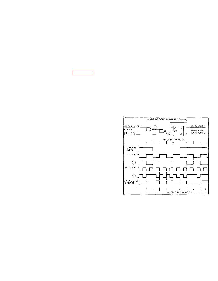
The output from the
NRZ to Cond
Diphase Conv
2X Clock Gate is ap-
plied as one clock
input to the NRZ to
Cond Diphase Conv.
The second clock
input is the normal
Clock signal. To-
gether, the two clock
inputs convert the
NRZ data input (where
logic 1 is a high
level and logic 0 a
low level) to con-
ditioned diphase
output (where a
transition occurs for
every bit period and
a logic O is a second transition one-half bit period later).
The output data is shifted one-half bit from the input data.
The Diphase output consists of two outputs, one the inverse
of the other. These outputs drive the balanced amplifiers.
The output from the NRZ to Cond Diphase Conv is applied to an
DIPHASE
amplifier and through a high-voltage protection circuit to the
OUT
DIPHASE OUT connectors.
1-11


