TM 11-6625-3041-30/TO 33A1-8-908-12
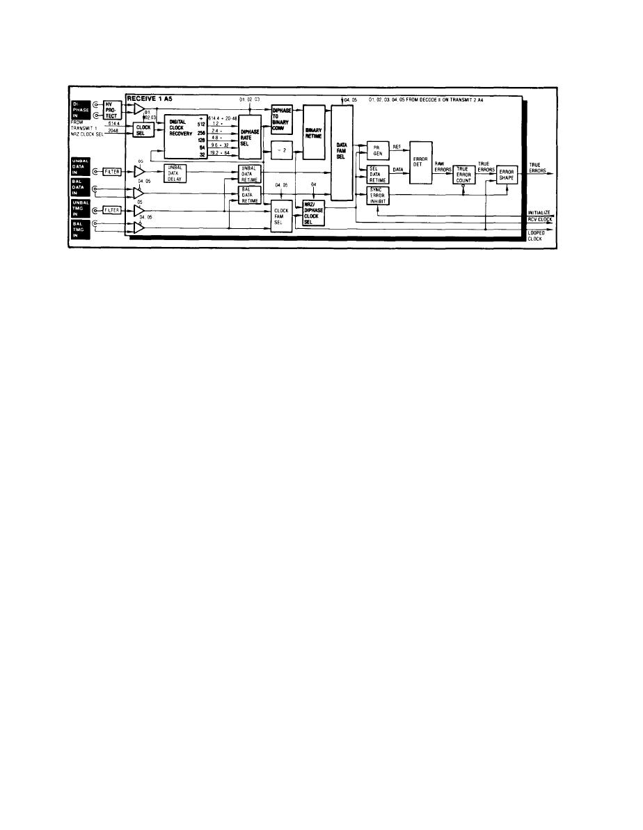
1-16. RECEIVE 1 (A5) DIPHASE IN
DIPHASE
The diphase signal is applied to the front panel DIPHASE IN
connector, through a high-voltage protection circuit, to
IN
an amplifier.
Clock Sel
The inputs to the Clock Sel are 614.4 kHz and 2048 kHz from the
NRZ Clock Sel on the Transmit 1 card. The 614.4 kHz input is
selected as the output by the DATA RATE control for the first
five settings (.6-9.6) through the 01, 02, and 03 outputs of the
Decode II. The 2048 kHz input is selected as the output for
the last two settings (16 and 32).
Digital
The data output from the DIPHASE IN amplifier and the clock
Clock
output from the Clock Sel are applied to the Digital Clock
Recover
Recovery. The Digital Clock Recovery has five different divider
outputs.
The actual output of the Digital Clock Recovery depends on the
output of the Clock Sel. For example, if the Clock Sel has been
set for 2048 kHz, the output of the 64 divider will be 32 kHz.
Each rate is twice the actual diphase DATA RATE setting because
two transitions are required for each logic 0 bit, one a half-
bit later than the other.
Diphase
The outputs from the five dividers in the Digital Clock Recovery
are applied to the input of the Diphase Rate Sel.
Rate Sel
The input selected as the output depends on the setting of the
DATA RATE control (through the 01, 02, and 03 outputs from
Decode II). For example, a Decode II output of 101 sets the
Diphase Rate Sel to 32 kHz, corresponding to a DATA RATE
setting of 16 kb/s.
Diphase to
The data output from the DIPHASE IN amplifier and the clock out-
Binary
put from the Diphase Rate Sel are applied to the input of the
Diphase to Binary Conv. The Diphase to Binary Conv converts
Conv
diphase data to binary data.


