
TM 11-6625-2948-14&P
OSCILLOSCOPE
AN/USM-281C
EL5YQ-9
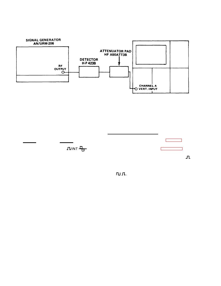
Modulation Characteristics Test Set-Up
e. Internal Pulse Modulation Test.
(6) Set the MD-1075/URM controls as follows:
(1) Connect test equipment as shown in figure 4-1.
Position
Control
EXT
FUNCTION
(2) Perform steps (2) through (5) of paragraph 4-4 b.
X1
RATE
(3) Set FUNCTION switch of the modulator to INT
and the SELECTOR switch to INT.
INT
SELECTOR
switch
to
(4) Set
MODULATION
SELECTOR
Fully clockwise
RATE Vernier
EXT
(7) Set the oscilloscope for a square wave display.
(5) Set SYNC DELAY multiplier to LOW and SYNC
DELAY vernier control fully counterclockwise.
(8) Slowly rotate the RATE control vernier counterclock-
wise and observe the display on the oscilloscope. The
( 6 ) Set RATE control fully clockwise and the RATE
multiplier to X1.
square wave rate should decrease smoothly below 40 Hz
to a minimum of typically 10 Hz.
(7) Set PULSE WIDTH multiplier switch to X10 and set
(9) Set the RATE multiplier control to X100.
the PULSE WIDTH vernier control fully counterclockwise.
Set oscilloscope for stable display of the pulsed signal.
(10) Slowly rotate the RATE control vernier of the modu-
l a t o r clockwise. The display should increase smoothly
(8) Rotate the RATE control vernier slowly counterclock-
wise and observe the display on the oscilloscope. The pulse
beyond a rate of 4000 Hz.
repetition rate should decrease smoothly below 40 Hz to a
(11) Repeat steps (1) through (10) at 9.0 and 11.0 GHz.
minimum of typically 10 Hz.

