
TM11-6625-2948-14+P
(4) Adjust ATTENUATOR control for 0 dBm RF output
(7) Set oscilloscope for stable display of RF detected
power and set MODULATION SELECTOR to EXT
.
p u l s e s (Channel A), and external synchronizing signal
(Channel B) simultaneously.
(5) Set controls on MD-1075/URM as follows:
(8) Check that the RF detected pulses in Channel A are
Control
Position
synchronized and stable as the frequency range of the
oscillator is varied from 40 Hz to 4000 Hz.
FUNCTION
lNT
T
(9) Repeat steps (6) through (9) for ELGAR 501A
SELECTOR
EXT (+)
AMPLITUDE control set to 50 volts rms.
PULSE WIDTH
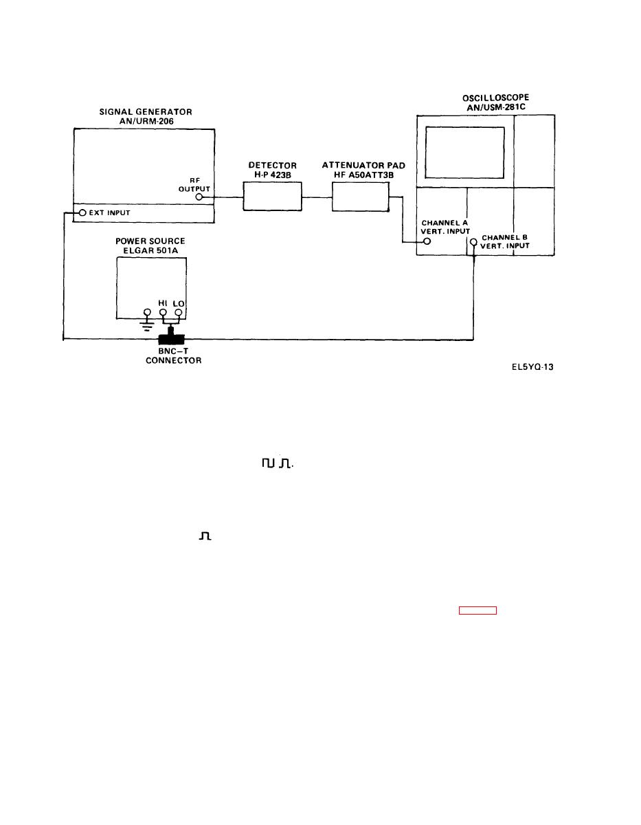
j. External Synchronization Pulse Test.
Multiplier
X10
(1) Set up equipment as shown in Fig. 4-2.
PULSE WIDTH
Vernier
Fully Clockwise
( 6 ) Set AMPLITUDE control of ELGAR 501A
( 3 ) Set MODULATION SELECTOR switch to CW and
to 5 volts rms (14 volts peak to peak) at 40 Hz by monitor-
adjust the POWER SET control for an indication of CAL
ing Channel B of Oscilloscope AN/USM-281C.
on the power level monitor meter.

